M20F-FXS, M20G-FXS ENGINE MECHANICAL CYLINDER HEAD REASSEMBLY
CAUTION / NOTICE / HINT
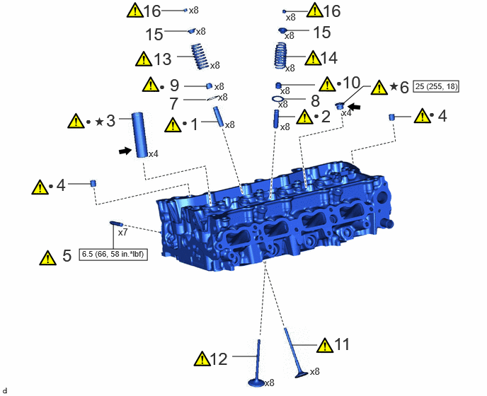


|
N*m (kgf*cm, ft.*lbf): Specified torque | ● | Non-reusable part |

|
MP grease | ★ | Precoated part |
PROCEDURE

 11122
1.INSTALL INTAKE VALVE GUIDE BUSH
11122
1.INSTALL INTAKE VALVE GUIDE BUSH
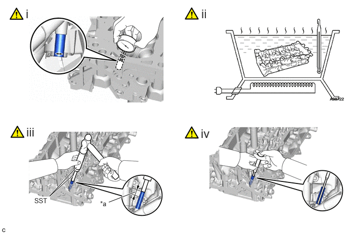
| *a | Protrusion Height | - | - |
Using a caliper gauge, measure the intake valve guide bush bore diameter of the cylinder head sub-assembly.
- Standard Intake Valve Guide Bush Bore Diameter:
10.285 to 10.306 mm (0.405 to 0.406 in.)
| Bush Size | Specified Condition |
|---|---|
| STD | 10.333 to 10.344 mm (0.40681 to 0.40724 in.) |
| O/S 0.05 | 10.383 to 10.394 mm (0.40878 to 0.40921 in.) |
- Standard Bush Length:
41.3 to 41.7 mm (1.63 to 1.64 in.)
- HINT:
- ·
If the intake valve guide bush bore diameter of the cylinder head sub-assembly is more than 10.306 mm (0.406 in.), machine the intake valve guide bush bore of the cylinder head sub-assembly to a dimension of 10.335 to 10.356 mm (0.407 to 0.408 in.) to install an O/S 0.05 intake valve guide bush.
·If the intake valve guide bush bore diameter of the cylinder head sub-assembly is more than 10.356 mm (0.408 in.), replace the cylinder head sub-assembly.
Heat the cylinder head sub-assembly to between 80 and 100°C (176 and 212°F).
- CAUTION:
-
Be sure to wear protective gloves.
Using SST and a hammer, tap in the selected intake valve guide bush.
- SST
- 09201-10000 (09201-01050)
09950-70010 (09951-07100)
- Standard Protrusion Height:
13.35 to 13.60 mm (0.526 to 0.535 in.)
Using a sharp 5.5 mm reamer, ream the intake valve guide bush to obtain the standard oil clearance.
- Standard Oil Clearance:
0.025 to 0.060 mm (0.000984 to 0.00236 in.)
11126
2.INSTALL EXHAUST VALVE GUIDE BUSH
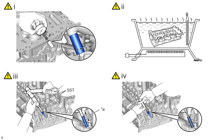
| *a | Protrusion Height | - | - |
Using a caliper gauge, measure the intake valve guide bush bore diameter of the cylinder head sub-assembly.
- Standard Intake Valve Guide Bush Bore Diameter:
10.285 to 10.306 mm (0.405 to 0.406 in.)
| Bush Size | Specified Condition |
|---|---|
| STD | 10.333 to 10.344 mm (0.40681 to 0.40724 in.) |
| O/S 0.05 | 10.383 to 10.394 mm (0.40878 to 0.40921 in.) |
- Standard Bush Length:
43.3 to 43.7 mm (1.70 to 1.72 in.)
- HINT:
- ·
If the intake valve guide bush bore diameter of the cylinder head sub-assembly is more than 10.306 mm (0.406 in.), machine the intake valve guide bush bore of the cylinder head sub-assembly to a dimension of 10.335 to 10.356 mm (0.407 to 0.408 in.) to install an O/S 0.05 intake valve guide bush.
·If the intake valve guide bush bore diameter of the cylinder head sub-assembly is more than 10.356 mm (0.408 in.), replace the cylinder head sub-assembly.
Heat the cylinder head sub-assembly to between 80 and 100°C (176 and 212°F).
- CAUTION:
-
Be sure to wear protective gloves.
Using SST and a hammer, tap in the selected intake valve guide bush.
- SST
- 09201-10000 (09201-01050)
09950-70010 (09951-07100)
- Standard Protrusion Height:
13.75 to 14.00 mm (0.541 to 0.551 in.)
Using a sharp 5.5 mm reamer, ream the intake valve guide bush to obtain the standard oil clearance.
- Standard Oil Clearance:
0.030 to 0.065 mm (0.00118 to 0.00256 in.)
3.INSTALL SPARK PLUG TUBE

|
|
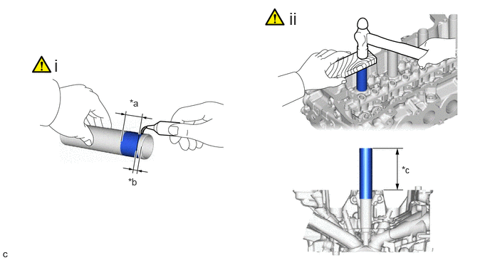
| *a | 1.0 to 7.0 mm (0.0394 to 0.276 in.) | *b | 1.0 mm (0.0394 in.) |
| *c | Protrusion Height | - | - |
Apply adhesive to 4 new spark plug tubes as shown in the illustration.
- Adhesive:
Toyota Genuine Adhesive 1324, Three Bond 1324 or equivalent
- NOTICE:
- ·
Install the spark plug tubes within 3 minutes of applying adhesive.
·Be careful not to deform the spark plug tubes.
·Do not expose the spark plug tubes to engine oil for at least 1 hour after installing them.
Using a wooden block and hammer, tap in the 4 spark plug tubes to the specified protrusion height.
- Standard Protrusion Height:
77.3 to 78.3 mm (3.04 to 3.08 in.)
- NOTICE:
-
To avoid tapping in the spark plug tube too far, measure the protrusion height while tapping it.
11115A
4.INSTALL RING PIN
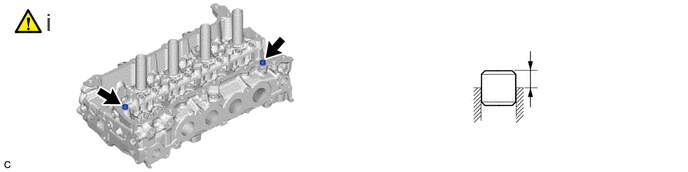
Using a plastic hammer, tap in 2 new ring pins to the specified protrusion height.
- Standard Protrusion Height:
6.5 to 7.5 mm (0.256 to 0.295 in.)
17159
5.INSTALL STUD BOLT
|
|
|
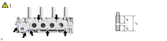
| *a | 20 mm (0.787 in.) | *b | 13 mm (0.512 in.) |
| *c | 35 mm (1.38 in.) | - | - |
Using an E8 "TORX" socket wrench, install the 7 stud bolts.
- Torque:
- 6.5 N*m (66 kgf*cm, 58 in.*lbf)
11117E
6.INSTALL NO. 1 STRAIGHT SCREW PLUG
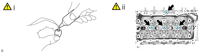
Apply adhesive to the 4 No. 1 straight screw plugs.
- Adhesive:
Toyota Genuine Adhesive 1324, Three Bond 1324 or equivalent
- NOTICE:
-
Install the No. 1 straight screw plugs within 3 minutes of applying adhesive.
Using a 6 mm hexagon wrench, install the 4 No. 1 straight screw plugs to the cylinder head sub-assembly.
- Torque:
- 25 N*m (255 kgf*cm, 18 ft.*lbf)
13734A
7.INSTALL INTAKE VALVE SPRING SEAT (for Intake Side)
13734B
8.INSTALL EXHAUST VALVE SPRING SEAT (for Exhaust Side)
13711E
9.INSTALL INTAKE VALVE STEM OIL SEAL (for Intake Side)
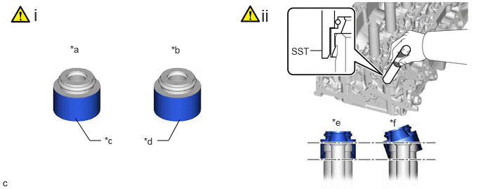
| *a | Intake Valve Stem Oil Seal | *b | Exhaust Valve Stem Oil Seal |
| *c | Gray | *d | Black |
| *e | Correct | *f | Incorrect |
Apply a light coat of engine oil to 8 new valve stem oil seals.
- NOTICE:
-
Make sure to install each valve stem oil seal to the correct side. Installing an intake valve stem oil seal to the exhaust side or installing an exhaust valve stem oil seal to the intake side can cause installation problems later.
- HINT:
-
The intake valve stem oil seals are gold and the exhaust valve stem oil seals are gray.
Using SST, push in the 8 valve stem oil seals.
- SST
- 09201-41020
- NOTICE:
- ·
Failure to use SST will cause the valve stem oil seals to be damaged or improperly seated.
·Do not push in the valve stem oil seals at an angle.
13715A
10.INSTALL EXHAUST VALVE STEM OIL SEAL (for Exhaust Side)
Perform the same procedure as for the intake side.
13711
11.INSTALL INTAKE VALVE
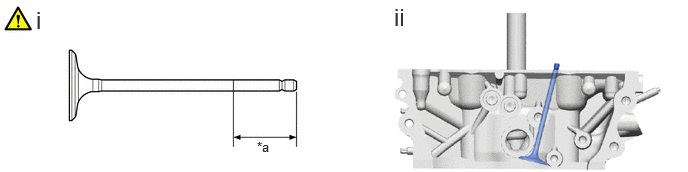
| *a | 30 mm (1.18 in.) or more | - | - |
Sufficiently apply engine oil to the tip area of the intake valve shown in the illustration.
Install the 8 intake valves to the cylinder head sub-assembly.
13715
12.INSTALL EXHAUST VALVE
Perform the same procedure as for the intake side.
13711M
13.INSTALL INTAKE VALVE COMPRESSION SPRING (for Intake Side)
|
|
|
13715H
14.INSTALL EXHAUST VALVE COMPRESSION SPRING (for Exhaust Side)
|
|
|
13741B
15.INSTALL VALVE SPRING RETAINER
13741A
16.INSTALL VALVE SPRING RETAINER LOCK
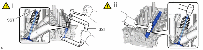
Using SST, compress the inner compression spring and install the 8 valve spring retainer locks.
- SST
- 09202-70020 (09202-01010, 09202-01020)
09202-00021
Using a plastic hammer, lightly tap the valve stem tip to ensure a proper fit.
- NOTICE:
- ·
Be careful not to damage the valve stem tip.
·Be careful not to damage the valve spring retainer.