M20F-FXS, M20G-FXS ENGINE MECHANICAL ENGINE UNIT REASSEMBLY
CAUTION / NOTICE / HINT
- NOTICE:
-
This procedure includes the installation of small-head bolts. Refer to Small-Head Bolts of Basic Repair Hint to identify the small-head bolts.
CAUTION / NOTICE / HINT
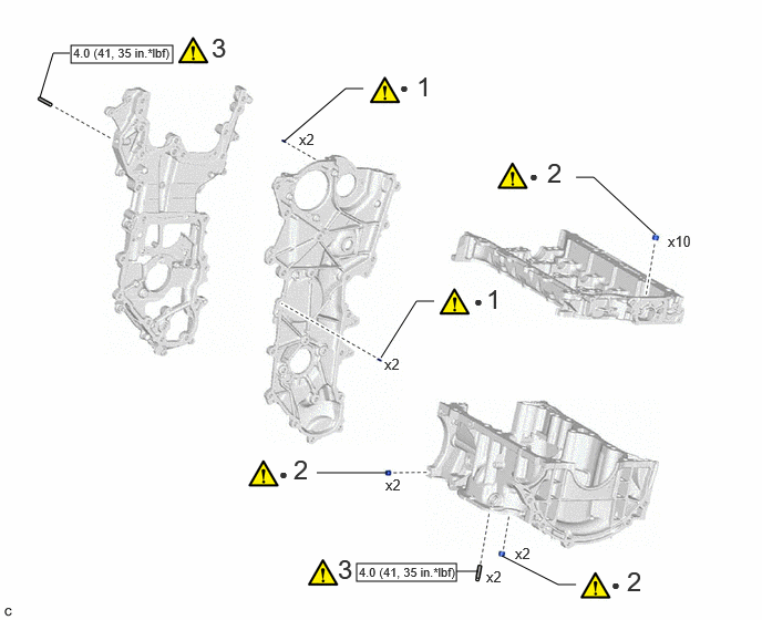
| Procedure | Part Name Code | 
|

|

|
|
|---|---|---|---|---|---|
| 1 | STRAIGHT PIN | - | ( 202307,999999,_51,_144958,_0604254,RM100000002BTSC_01_0136,) 202307,999999,_51,_144958,_0604254,RM100000002BTSC_01_0136,)
|
- | - |
| 2 | RING PIN | - | (202307,999999,_51,_144958,_0604254,RM100000002BTSC_01_0054,)
|
- | - |
| 3 | STUD BOLT | - | (202307,999999,_51,_144958,_0604254,RM100000002BTSC_01_0093,)
|
- | - |

|
N*m (kgf*cm, ft.*lbf): Specified torque | ● | Non-reusable part |
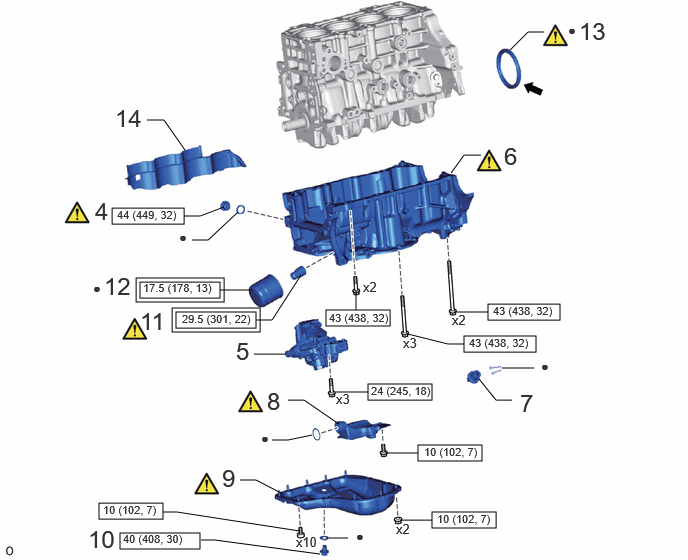
| Procedure | Part Name Code |
|
|
|
|
|---|---|---|---|---|---|
| 4 | STRAIGHT SCREW PLUG | - | (202307,999999,_51,_144958,_0604254,RM100000002BTSC_01_0113,)
|
- | - |
| 5 | OIL PUMP ASSEMBLY | 15100 | - | - | - |
| 6 | STIFFENING CRANKCASE ASSEMBLY | 11420 | (202307,999999,_51,_144958,_0604254,RM100000002BTSC_01_0041,)
|
- | - |
| 7 | CRANKCASE CAP ASSEMBLY | 15520B | - | - | - |
| 8 | OIL STRAINER SUB-ASSEMBLY | 15104 | (202307,999999,_51,_144958,_0604254,RM100000002BTSC_01_0043,)
|
- | - |
| 9 | OIL PAN SUB-ASSEMBLY | 12101 | (202307,999999,_51,_144958,_0604254,RM100000002BTSC_01_0044,)
|
- | - |
| 10 | OIL PAN DRAIN PLUG | 12101A | - | - | - |
| 11 | OIL FILTER UNION | 15600A | (202307,999999,_51,_144958,_0604254,RM100000002BTSC_01_0115,)
|
- | - |
| 12 | OIL FILTER SUB-ASSEMBLY | 15601 | - | - | - |
| 13 | REAR ENGINE OIL SEAL | 11401L | (202307,999999,_51,_144958,_0604254,RM100000002BTSC_01_0050,)
|
- | - |
| 14 | CYLINDER BLOCK WATER JACKET SPACER | 11445 | - | - | - |

|
Tightening torque for "Major areas involving basic vehicle performance such as moving/turning/stopping" : N*m (kgf*cm, ft.*lbf) |
|
N*m (kgf*cm, ft.*lbf): Specified torque |

|
MP grease | ● | Non-reusable part |
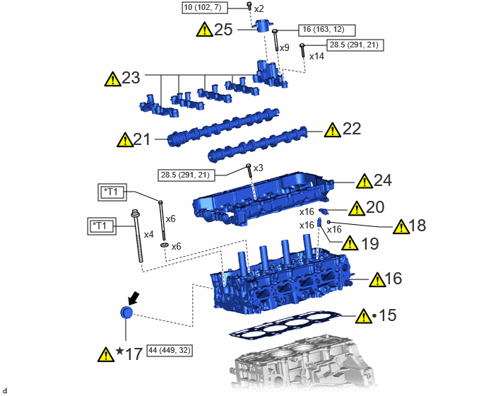
|
|
Tightening torque for "Major areas involving basic vehicle performance such as moving/turning/stopping" : N*m (kgf*cm, ft.*lbf) |
|
N*m (kgf*cm, ft.*lbf): Specified torque |
| ● | Non-reusable part |
|
Adhesive 1324 |
| ★ | Precoated part | - | - |
| *T1 | 1st: 50 (510, 37)
2nd: Turn 90° 3rd: Turn 90° |
- | - |
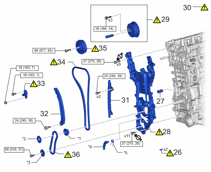
| Procedure | Part Name Code |
|
|
|
|
|---|---|---|---|---|---|
| 26 | CRANKSHAFT TIMING GEAR KEY | 13471A | (202307,999999,_51,_144958,_0604254,RM100000002BTSC_01_0135,)
|
- | - |
| 27 | OIL NOZZLE VALVE SUB-ASSEMBLY | 15703A | - | - | - |
| 28 | TIMING CHAIN COVER ASSEMBLY | 11310 | (202307,999999,_51,_144958,_0604254,RM100000002BTSC_01_0121,)
|
- | - |
| 29 | CAMSHAFT TIMING EXHAUST GEAR ASSEMBLY | 13070A | (202307,999999,_51,_144958,_0604254,RM100000002BTSC_01_0153,)
|
- | - |
| 30 | NO. 1 CYLINDER TO TDC (COMPRESSION) | - | (202307,999999,_51,_144958,_0604254,RM100000002BTSC_01_0154,)
|
- | - |
| 31 | NO. 1 CHAIN VIBRATION DAMPER | 13561 | - | - | - |
| 32 | CHAIN TENSIONER SLIPPER | 13559 | - | - | - |
| 33 | NO. 1 CHAIN TENSIONER ASSEMBLY | 13540 | (202307,999999,_51,_144958,_0604254,RM100000002BTSC_01_0157,)
|
- | - |
| 34 | CHAIN SUB-ASSEMBLY | 13506 | (202307,999999,_51,_144958,_0604254,RM100000002BTSC_01_0158,)
|
- | - |
| 35 | CAMSHAFT TIMING GEAR ASSEMBLY | 13050 | (202307,999999,_51,_144958,_0604254,RM100000002BTSC_01_0159,)
|
- | - |
| 36 | OIL PUMP DRIVE CHAIN SUB-ASSEMBLY | 13507A | (202307,999999,_51,_144958,_0604254,RM100000002BTSC_01_0139,)
|
- | - |
| *1 | CRANKSHAFT TIMING SPROCKET | *2 | OIL PUMP DRIVE SPROCKET |
| *3 | OIL PUMP DRIVE SHAFT SPROCKET | *4 | CHAIN TENSIONER PLATE |
| *5 | CHAIN DAMPER SPRING | - | - |
|
|
N*m (kgf*cm, ft.*lbf): Specified torque | 
|
Do not apply lubrications to the threaded parts |
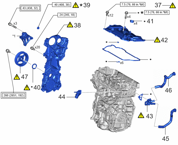
| Procedure | Part Name Code |
|
|
|
|
|---|---|---|---|---|---|
| 37 | NO. 1 CYLINDER TO TDC (COMPRESSION) | - | (202307,999999,_51,_144958,_0604254,RM100000002BTSC_01_0110,)
|
- | - |
| 38 | NO. 2 TIMING CHAIN COVER ASSEMBLY | 11320B | (202307,999999,_51,_144958,_0604254,RM100000002BTSC_01_0124,)
|
- | - |
| 39 | STRAIGHT SCREW PLUG | - | (202307,999999,_51,_144958,_0604254,RM100000002BTSC_01_0123,)
|
- | - |
| 40 | TIMING CHAIN COVER OIL SEAL | 11301C | (202307,999999,_51,_144958,_0604254,RM100000002BTSC_01_0018,)
|
- | - |
| 41 | SPARK PLUG TUBE GASKET | 11193 | - | - | - |
| 42 | CYLINDER HEAD COVER SUB-ASSEMBLY | 11201 | (202307,999999,_51,_144958,_0604254,RM100000002BTSC_01_0020,)
|
- | - |
| 43 | WATER BY-PASS OUTLET | 16351 | (202307,999999,_51,_144958,_0604254,RM100000002BTSC_01_0126,)
|
- | - |
| 44 | WATER OUTLET SUB-ASSEMBLY | 16304 | - | - | - |
| 45 | OUTLET HEATER WATER HOSE | - | - | - | - |
| 46 | INLET HEATER WATER HOSE | - | - | - | - |
| 47 | CRANKSHAFT PULLEY ASSEMBLY | 13470 | (202307,999999,_51,_144958,_0604254,RM100000002BTSC_01_0021,)
|
- | - |
|
|
Tightening torque for "Major areas involving basic vehicle performance such as moving/turning/stopping" : N*m (kgf*cm, ft.*lbf) |
|
N*m (kgf*cm, ft.*lbf): Specified torque |
| ● | Non-reusable part | ★ | Precoated part |
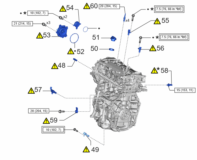
| Procedure | Part Name Code |
|
|
|
|
|---|---|---|---|---|---|
| 48 | PCV VALVE (VENTILATION VALVE SUB-ASSEMBLY) | 12204C | (202307,999999,_51,_144958,_0604254,RM100000002BTSC_01_0032,)
|
- | - |
| 49 | CRANKSHAFT POSITION SENSOR | 11401G | (202307,999999,_51,_144958,_0604254,RM100000002BTSC_01_0022,)
|
- | - |
| 50 | OIL FILLER CAP GASKET | 12108A | - | - | - |
| 51 | OIL FILLER CAP ASSEMBLY | 12180E | - | - | - |
| 52 | CAM TIMING CONTROL MOTOR O-RING | 13090E | - | - | - |
| 53 | CAM TIMING CONTROL MOTOR WITH EDU ASSEMBLY | 13090D | (202307,999999,_51,_144958,_0604254,RM100000002BTSC_01_0130,)
|
- | - |
| 54 | CAM TIMING OIL CONTROL SOLENOID ASSEMBLY | 15370 | (202307,999999,_51,_144958,_0604254,RM100000002BTSC_01_0131,)
|
- | - |
| 55 | CAMSHAFT POSITION SENSOR (for Exhaust Side) | 11102A | (202307,999999,_51,_144958,_0604254,RM100000002BTSC_01_0163,)
|
- | - |
| 56 | CAMSHAFT POSITION SENSOR (for Intake Side) | 11102A | (202307,999999,_51,_144958,_0604254,RM100000002BTSC_01_0162,)
|
- | - |
| 57 | OIL PRESSURE CONTROL VALVE ASSEMBLY | 15250 | (202307,999999,_51,_144958,_0604254,RM100000002BTSC_01_0034,)
|
- | - |
| 58 | OIL PRESSURE AND TEMPERATURE SENSOR | 89448D | (202307,999999,_51,_144958,_0604254,RM100000002BTSC_01_0132,)
|
- | - |
| 59 | KNOCK CONTROL SENSOR | 89615 | (202307,999999,_51,_144958,_0604254,RM100000002BTSC_01_0097,)
|
- | - |
| 60 | SPARK PLUG | 19100P | (202307,999999,_51,_144958,_0604254,RM100000002BTSC_01_0035,)
|
- | - |
|
|
Tightening torque for "Major areas involving basic vehicle performance such as moving/turning/stopping" : N*m (kgf*cm, ft.*lbf) |
|
N*m (kgf*cm, ft.*lbf): Specified torque |
| ● | Non-reusable part | ★ | Precoated part |
PROCEDURE

 1.INSTALL STRAIGHT PIN
|
|
|
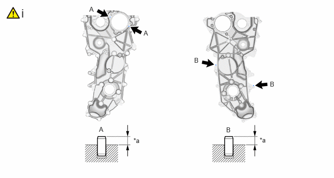
| *a | Protrusion Height | - | - |
Using a plastic hammer, tap in 4 new straight pins to the No. 2 timing chain cover assembly.
- Standard Protrusion Height:
- Straight Pin (A):
3.0 to 5.0 mm (0.118 to 0.197 in.)
- Straight Pin (B):
5.0 to 7.0 mm (0.197 to 0.276 in.)
2.INSTALL RING PIN
|
|
|

| *a | Protrusion Height | - | - |
Using a plastic hammer, tap in 14 new ring pins to the stiffening crankcase assembly.
- Standard Protrusion Height:
- Ring Pin (A):
3.5 to 4.5 mm (0.138 to 0.177 in.)
- Ring Pin (B):
3.2 to 4.3 mm (0.126 to 0.169 in.)
3.INSTALL STUD BOLT
|
|
|
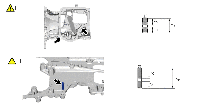
| *a | 9 mm (0.354 in.) | *b | 19 mm (0.748 in.) |
| *c | 21 mm (0.827 in.) | *d | 9 mm (0.354 in.) |
| *e | 34 mm (1.34 in.) | - | - |
Using an E6 "TORX" socket wrench, install the 2 stud bolts to the stiffening crankcase assembly.
- Torque:
- 4.0 N*m (41 kgf*cm, 35 in.*lbf)
Using an E6 "TORX" socket wrench, install the stud bolt to the timing chain cover assembly.
- Torque:
- 4.0 N*m (41 kgf*cm, 35 in.*lbf)
4.INSTALL STRAIGHT SCREW PLUG
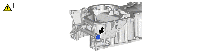
Using a 10 mm hexagon socket wrench, install the straight screw plug and a new gasket to the stiffening crankcase assembly.
- Torque:
- 44 N*m (449 kgf*cm, 32 ft.*lbf)
15100
5.INSTALL OIL PUMP ASSEMBLY
11420
6.INSTALL STIFFENING CRANKCASE ASSEMBLY
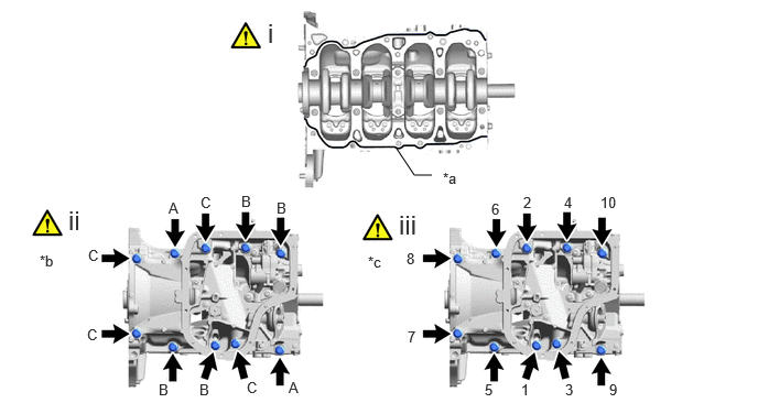
| *a | Seal Packing | *b | Bolt Type |
| *c | Tightening Order | - | - |
Apply seal packing in a continuous line as shown in the illustration.
- Seal Packing:
Toyota Genuine Seal Packing Black, Three Bond 1207B or equivalent
- Standard Seal Packing Dimension:
Area Specified Condition Continuous Line 2.5 to 3.5 mm (0.0984 to 0.138 in.)
- NOTICE:
- ·
Remove any oil from the contact surfaces.
·Install the stiffening crankcase assembly within 3 minutes and tighten the bolts within 15 minutes of applying seal packing.
·Do not add engine oil for at least 2 hours after the installation.
·Make sure that the diameter at the start and end of each line of seal packing is 5 +/- 2 mm (0.197 +/- 0.0787 in.).
Temporarily install the stiffening crankcase assembly with the 11 bolts.
- Bolt Length :
Item Length Bolt (A) 40 mm (1.57 in.) Bolt (B) 90 mm (3.54 in.) Bolt (C) 170 mm (6.69 in.)
Tighten the 11 bolts in the order shown in the illustration to install the stiffening crankcase assembly.
- Torque:
- 43 N*m (438 kgf*cm, 32 ft.*lbf)
15520B
7.INSTALL CRANKCASE CAP ASSEMBLY
15104
8.INSTALL OIL STRAINER SUB-ASSEMBLY
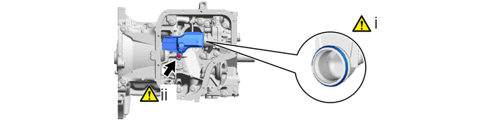
Apply a light coat of engine oil to a new oil strainer gasket.
Using an 8 mm socket wrench, install the oil strainer sub-assembly and oil strainer gasket to the stiffening crankcase assembly with the bolt.
- Torque:
- 10 N*m (102 kgf*cm, 7 ft.*lbf)
12101
9.INSTALL OIL PAN SUB-ASSEMBLY
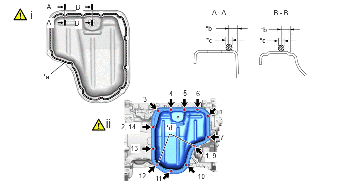
| *a | Seal Packing | *b | 4.5 mm (0.177 in.) |
| *c | 2.5 to 3.5 mm (0.0984 to 0.138 in.) | *d | Nut |
Apply seal packing in a continuous line as shown in the illustration.
- Seal Packing:
Toyota Genuine Seal Packing Black, Three Bond 1207B or equivalent
- Standard Seal Packing Diameter:
2.5 to 3.5 mm (0.0984 to 0.138 in.)
- NOTICE:
- ·
Remove any oil from the contact surfaces.
·Install the oil pan sub-assembly within 3 minutes and tighten the bolts and nuts within 10 minutes of applying seal packing.
·Do not start the engine for at least 2 hours after installation.
·Make sure that the diameter at the start and end of each line of seal packing is 5 +/- 2 mm (0.197 +/- 0.0787 in.).
Install the oil pan sub-assembly with the 12 bolts and 2 nuts in several steps in the order shown in the illustration.
- Torque:
- 10 N*m (102 kgf*cm, 7 ft.*lbf)
12101A
10.INSTALL OIL PAN DRAIN PLUG
- Torque:
- 40 N*m (408 kgf*cm, 30 ft.*lbf)
15600A
11.INSTALL OIL FILTER UNION
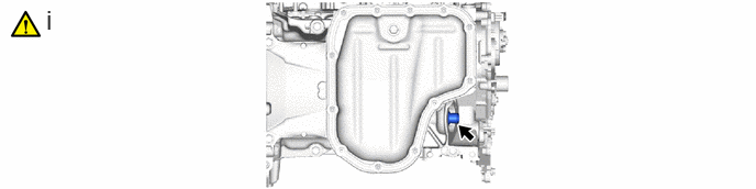
Using a 12 mm hexagon socket wrench, install the oil filter union to the stiffening crankcase assembly.
- Torque:
- 29.5 N*m (301 kgf*cm, 22 ft.*lbf)
15601
12.INSTALL OIL FILTER SUB-ASSEMBLY
11401L
13.INSTALL REAR ENGINE OIL SEAL
11445
14.INSTALL CYLINDER BLOCK WATER JACKET SPACER
11115
15.INSTALL CYLINDER HEAD GASKET
11101
16.INSTALL CYLINDER HEAD SUB-ASSEMBLY
|
|
|
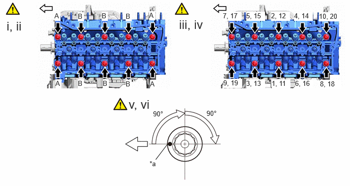
| *a | Paint Mark | - | - |

|
Front of Engine | - | - |
Place the cylinder head sub-assembly on the cylinder block sub-assembly.
- NOTICE:
- ·
Ensure that the contact surface of the cylinder head sub-assembly is free of oil.
·Place the cylinder head sub-assembly on the cylinder block sub-assembly gently in order not to damage the cylinder head gasket with the bottom of the cylinder head sub-assembly.
Install the 6 plate washers to the 10 cylinder head set bolts.
- Bolt Length :
Item Length Bolt (A) 129.1 to 130.9 mm (5.08 to 5.15 in.) Bolt (B) 139.1 to 140.9 mm (5.48 to 5.55 in.)
Apply a light coat of engine oil to the threads and under the heads of the cylinder head set bolts.
Step 1:
Using a 12 mm socket wrench, install and uniformly tighten the 10 cylinder head set bolts in several steps in the order shown in the illustration.
- Torque:
- 50 N*m (510 kgf*cm, 37 ft.*lbf)
- NOTICE:
-
Be careful not to drop the plate washers into the cylinder head sub-assembly.
Step 2:
Mark each cylinder head set bolt head with paint as shown in the illustration.
Tighten the cylinder head set bolts 90° in the order shown in step 1.
Step 3:
Tighten the cylinder head set bolts another 90° in the order shown in step 1.
Check that the paint marks are now facing rearward.
- HINT:
-
Perform "Inspection After Repair" after replacing the cylinder head sub-assembly.
11117G
17.INSTALL NO. 3 HEAD WITH STRAIGHT SCREW PLUG
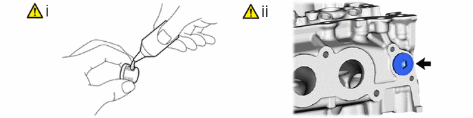
Apply adhesive to the No. 3 head with straight screw plug.
- Adhesive:
Toyota Genuine Adhesive 1324, Three Bond 1324 or equivalent
Using a 10 mm hexagon wrench, install the No. 3 head with straight screw plug to the cylinder head sub-assembly.
- Torque:
- 44 N*m (449 kgf*cm, 32 ft.*lbf)
- NOTICE:
- ·
install the No. 3 head with straight screw plug within 3 minutes of applying adhesive.
·Do not add engine oil for at least 1 hours after installation.
13716
18.INSTALL VALVE STEM CAP
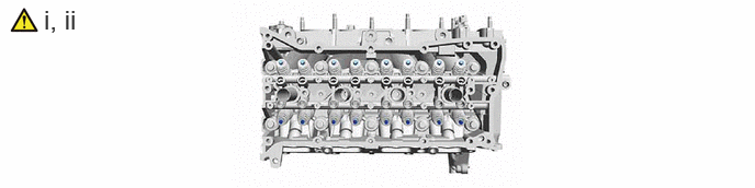
Apply a light coat of engine oil to the valve stem cap ends.
Install the 16 valve stem caps to the cylinder head sub-assembly.
- NOTICE:
- ·
Install the same parts in the same combination to their original locations.
·Do not drop the valve stem caps into the cylinder head sub-assembly.
13750
19.INSTALL VALVE LASH ADJUSTER ASSEMBLY
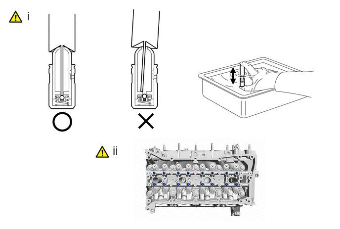
Inspect the 16 valve lash adjuster assemblies before installing them.
Install the 16 valve lash adjuster assemblies to the cylinder head sub-assembly.
- NOTICE:
-
Install the same parts in the same combination to their original locations.
13801
20.INSTALL NO. 1 VALVE ROCKER ARM SUB-ASSEMBLY
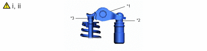
| *1 | No. 1 Valve Rocker Arm Sub-assembly | *2 | Valve Lash Adjuster Assembly |
| *3 | Valve Stem Cap | - | - |
Apply engine oil to the valve lash adjuster assembly tips and valve stem caps.
Install the 16 No. 1 valve rocker arm sub-assemblies as shown in the illustration.
- NOTICE:
-
Install the same parts in the same combination to their original locations.
13502B
21.INSTALL EXHAUST CAMSHAFT SUB-ASSEMBLY
|
|
|
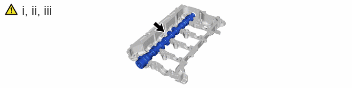
Clean the camshaft journals and camshaft housing sub-assembly.
Apply a light coat of engine oil to the camshaft journals and camshaft housing sub-assembly.
Install the exhaust camshaft sub-assembly to the camshaft housing sub-assembly.
13501A
22.INSTALL INTAKE CAMSHAFT SUB-ASSEMBLY
|
|
|
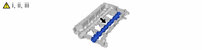
Clean the camshaft journals, camshaft housing sub-assembly and camshaft bearing caps.
Apply a light coat of engine oil to the camshaft journals, camshaft housing sub-assembly and camshaft bearing caps.
Install the intake camshaft sub-assembly to the camshaft housing sub-assembly.
23.INSTALL CAMSHAFT BEARING CAP
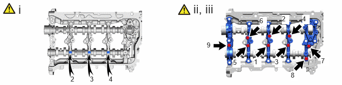
Place the No. 1 camshaft bearing cap, No. 2 camshaft bearing cap, 2 No. 3 camshaft bearing caps and No. 4 camshaft bearing cap in their correct locations.
Uniformly tighten the 9 bolts in the order shown in the illustration.
Check the torque of each bolt again.
11103
24.INSTALL CAMSHAFT HOUSING SUB-ASSEMBLY
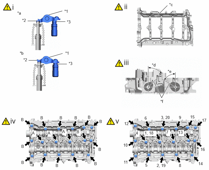
| *1 | No. 1 Valve Rocker Arm Sub-assembly | *2 | Valve Stem Cap |
| *3 | Valve Lash Adjuster Assembly | - | - |
| *a | Incorrect | *b | Correct |
| *c | Seal Packing | *d | 17° to 47° |
| *e | 42° to 72° | *f | No. 1 Cylinder Cam Nose |
Check that the No. 1 valve rocker arm sub-assemblies are installed as shown in the illustration.
Apply seal packing in a continuous line as shown in the illustration.
- Seal Packing:
Toyota Genuine Seal Packing Black, Three Bond 1207B or equivalent
- Standard Seal Packing Diameter:
3.0 to 4.0 mm (0.118 to 0.157 in.)
- NOTICE:
- ·
Remove any oil from the contact surfaces.
·Install the camshaft housing sub-assembly within 3 minutes and tighten the bolts within 10 minutes of applying seal packing.
·Do not start the engine for at least 2 hours after installation.
·Make sure that the diameter at the start and end of each line of seal packing is 5 +/- 2 mm (0.197 +/- 0.0787 in.).
Position the intake camshaft sub-assembly and exhaust camshaft sub-assembly as shown in the illustration.
Temporarily install the camshaft housing sub-assembly with the 17 bolts.
- Bolt Length :
Item Length Bolt (A) 40 mm (1.57 in.) Bolt (B) 65 mm (2.56 in.)
Install the camshaft housing sub-assembly, and then tighten the 17 bolts in several steps in the order shown in the illustration.
- Torque:
- 28.5 N*m (291 kgf*cm, 21 ft.*lbf)
- NOTICE:
- ·
Do not add engine oil for at least 2 hours after installation.
·Do not start the engine for at least 2 hours after installation.
·After installation, if the seal packing has seeped out, wipe it off.
23477
25.INSTALL FUEL PUMP LIFTER GUIDE
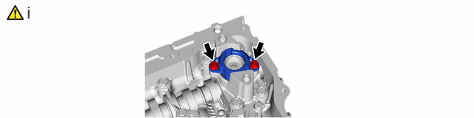
Using an 8 mm socket wrench, install the fuel pump lifter guide to the No. 4 camshaft bearing cap with the 2 bolts.
- Torque:
- 10 N*m (102 kgf*cm, 7 ft.*lbf)
13471A
26.INSTALL CRANKSHAFT TIMING GEAR KEY
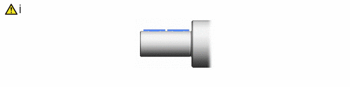
Using a plastic hammer, tap in the 2 crankshaft timing gear keys.
- HINT:
-
Tap in the crankshaft timing gear keys until they contact the crankshaft as shown in the illustration.
15703A
27.INSTALL OIL NOZZLE VALVE SUB-ASSEMBLY
11310
28.INSTALL TIMING CHAIN COVER ASSEMBLY
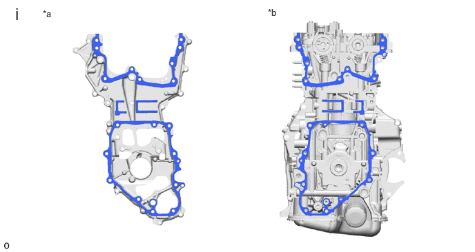
| *a | Timing Chain Cover Assembly Side | *b | Engine Assembly Side |
Clean the contact surfaces of the timing chain cover assembly, cylinder head sub-assembly, camshaft housing sub-assembly, cylinder block sub-assembly and stiffening crankcase assembly, and confirm that no oil, moisture, or other foreign matter is on the surfaces.
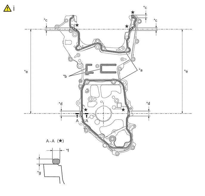
| *a | 2.5 to 3.5 mm (0.0984 to 0.138 in.) | *b | 2.0 to 6.0 mm (0.0787 to 0.236 in.) |
| *c | 10 mm (0.394 in.) | *d | 20 mm (0.787 in.) |
| *e | 344.2 mm (1.13 ft.) | *f | 4.0 to 6.0 mm (0.157 to 0.236 in.) |
| *g | 3.0 to 4.0 mm (0.118 to 0.157 in.) | - | - |

|
Seal Packing | - | - |
Apply seal packing to the timing chain cover assembly as shown in the illustration.
- Seal Packing:
Toyota Genuine Seal Packing Black, Three Bond 1207B or equivalent
- NOTICE:
- ·
Clean the surfaces with non-residue solvent before applying seal packing.
·Install the timing chain cover assembly within 3 minutes and tighten the bolts within 10 minutes of applying seal packing.
·Do not add oil for at least 2 hours after installation.
·Do not start the engine for at least 2 hours after installation.
·Make sure that the diameter at the start and end of each line of seal packing is 5 +/- 2 mm (0.197 +/- 0.0787 in.).
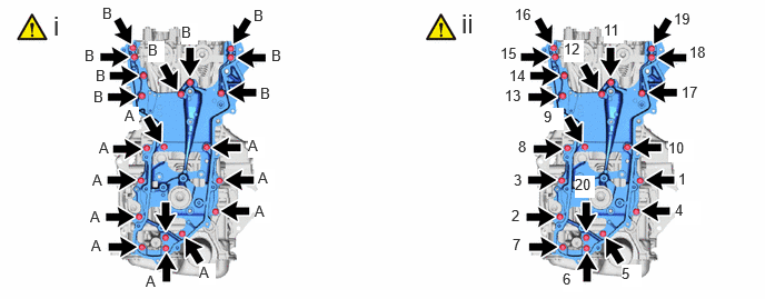
Temporarily install the timing chain cover assembly with the 20 bolts.
- Bolt Length:
Bolt Length (A) 30 mm (1.18 in.) (B) 45 mm (1.77 in.)
- NOTICE:
-
Make sure there is no oil on the bolts. If oil is found on any bolt, clean it before installation.
Tighten the 20 bolts in the order shown in the illustration.
- Torque:
- 27 N*m (275 kgf*cm, 20 ft.*lbf)
13070A
29.INSTALL CAMSHAFT TIMING EXHAUST GEAR ASSEMBLY
|
|
|
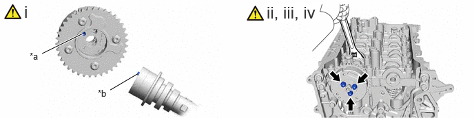
| *a | Knock Pin Hole | *b | Knock Pin |
Align and fit the knock pin of the exhaust camshaft sub-assembly to the knock pin hole of the camshaft timing exhaust gear assembly.
Using a wrench, hold the hexagonal portion of the exhaust camshaft sub-assembly.
- NOTICE:
-
Be careful not to damage the camshaft housing sub-assembly, cylinder head sub-assembly and spark plug tube with the wrench.
Using a 5 mm hexagon socket wrench, install the camshaft timing exhaust gear assembly and camshaft timing oil control valve assembly (exhaust camshaft timing gear bolt assembly) with the 3 bolts.
- Torque:
- 19 N*m (194 kgf*cm, 14 ft.*lbf)
- NOTICE:
-
Make sure to fit the protrusion of the camshaft timing oil control valve assembly (exhaust camshaft timing gear bolt assembly) into the cutout of the camshaft timing exhaust gear assembly.
Pull the camshaft timing oil control valve assembly (exhaust camshaft timing gear bolt assembly) to confirm that is installed securely.
30.SET NO. 1 CYLINDER TO TDC (COMPRESSION)
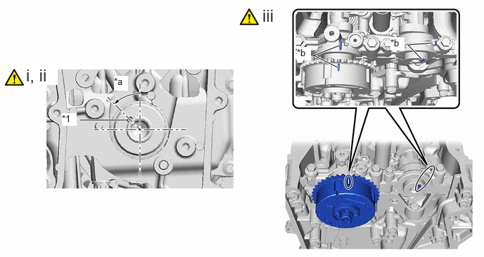
| *1 | Crankshaft Timing Gear Key | - | - |
| *a | 44.2° | *b | Timing Mark |
Temporarily install the crankshaft pulley bolt.
Rotate the crankshaft 44.2° counterclockwise to position the crankshaft timing gear key as shown in the illustration.
Check that the timing marks of the camshaft timing exhaust gear assembly and camshaft timing gear assembly are as shown in the illustration.
13561
31.INSTALL NO. 1 CHAIN VIBRATION DAMPER
- Torque:
- 24 N*m (245 kgf*cm, 18 ft.*lbf)
13559
32.INSTALL CHAIN TENSIONER SLIPPER
- Torque:
- 24 N*m (245 kgf*cm, 18 ft.*lbf)
13540
33.INSTALL NO. 1 CHAIN TENSIONER ASSEMBLY
|
|
|
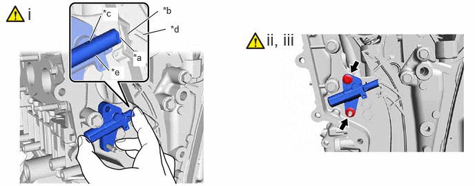
| *a | End of the plunger | *b | Groove |
| *c | Oil Hole | *d | No. 1 Chain Tensioner Slipper |
| *e | Plunger | - | - |
While slightly pushing in the plunger of the No. 1 chain tensioner assembly, install the No. 1 chain tensioner assembly.
- HINT:
- ·
Make sure that the end of the plunger is correctly seated in the groove of the No. 1 chain tensioner slipper.
·Make sure that the oil hole of the plunger is facing up.
Using an 8 mm socket wrench, install the bolt.
- Torque:
- 10 N*m (102 kgf*cm, 7 ft.*lbf)
Install the nut.
- Torque:
- 10 N*m (102 kgf*cm, 7 ft.*lbf)
13506
34.INSTALL CHAIN SUB-ASSEMBLY
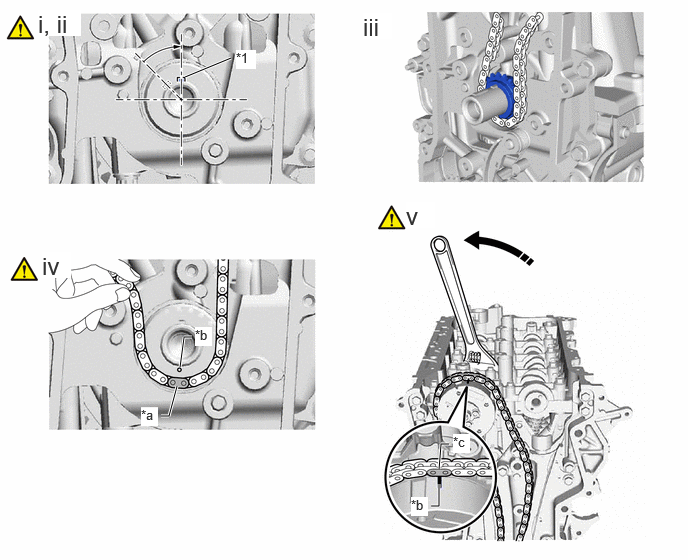
| *1 | Crankshaft Timing Gear Key | - | - |
| *a | Paint Mark (Yellow) | *b | Timing Mark |
| *c | Paint Mark (Orange) | - | - |

|
Turn | - | - |
Set the crankshaft timing gear key as shown in the illustration.
Remove the crankshaft pulley bolt.
Install the crankshaft timing sprocket and chain sub-assembly.
Align the paint mark (yellow) of the chain sub-assembly with the timing mark of the crankshaft timing sprocket and install the chain sub-assembly to the crankshaft timing sprocket.
Using the hexagonal portion of the exhaust camshaft sub-assembly, rotate the exhaust camshaft sub-assembly counterclockwise with a wrench, align the timing mark of the camshaft timing exhaust gear assembly with the paint mark (orange) of the chain sub-assembly, and install the chain sub-assembly to the camshaft timing exhaust gear assembly.
13050
35.INSTALL CAMSHAFT TIMING GEAR ASSEMBLY
|
|
|
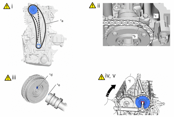
| *a | Loosen | *b | Paint Mark (Orange) |
| *c | Timing Mark | *d | Knock Pin Hole |
| *e | Knock Pin | *f | Hold |
|
|
Turn | - | - |
Hold the hexagonal portion of the exhaust camshaft sub-assembly with a wrench and turn the camshaft timing exhaust gear assembly clockwise to loosen the chain sub-assembly between the camshaft timing exhaust gear assembly and crankshaft timing sprocket as shown in the illustration.
Align the paint mark (orange) of the chain sub-assembly with the timing mark of the camshaft timing gear assembly and install the chain sub-assembly to the camshaft timing gear assembly.
Align and fit the knock pin of the intake camshaft sub-assembly to the knock pin hole of the camshaft timing gear assembly.
Using a wrench, hold the hexagonal portion of the intake camshaft sub-assembly.
- NOTICE:
- ·
Be careful not to damage the camshaft housing sub-assembly, cylinder head sub-assembly and spark plug tube with the wrench.
·Do not disassemble the camshaft timing gear assembly.
Using a 10 mm bi-hexagonal wrench, install the camshaft timing gear assembly with the bolt.
- Torque:
- 86 N*m (877 kgf*cm, 63 ft.*lbf)
13507A
36.INSTALL OIL PUMP DRIVE CHAIN SUB-ASSEMBLY
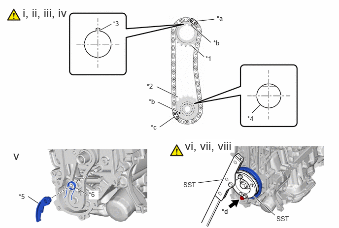
| *1 | Oil Pump Drive Sprocket | *2 | Oil Pump Drive Shaft Sprocket |
| *3 | Crankshaft Timing Gear Key | *4 | Oil Pump Sub-assembly |
| *5 | Chain Tensioner Plate | *6 | Chain Damper Spring |
| *a | Mark Plate (Yellow) | *b | Timing Mark |
| *c | Mark Plate (Orange) | *d | Bolt |
Set the crankshaft timing gear key as shown in the illustration.
Turn the oil pump drive shaft so that the flat face is facing upward.
Align the mark plates with the timing marks of the oil pump drive sprocket and oil pump drive shaft sprocket as shown in the illustration.
- HINT:
-
Make sure the mark plates of the oil pump drive chain sub-assembly are facing away from the engine assembly.
With the oil pump drive chain sub-assembly placed around the oil pump drive sprocket and oil pump drive shaft sprocket, install the oil pump drive sprocket to the crankshaft and temporarily install the oil pump drive shaft sprocket to the oil pump drive shaft.
Install the chain damper spring to the chain tensioner plate, and then install the chain tensioner plate.
Temporarily install the crankshaft pulley assembly with the crankshaft pulley bolt.
Using SST, hold the crankshaft pulley assembly and tighten the bolt.
- SST
- 09213-54015
09330-00021
- Torque:
- 50 N*m (510 kgf*cm, 37 ft.*lbf)
Remove SST, the crankshaft pulley bolt and crankshaft pulley assembly.
37.SET NO. 1 CYLINDER TO TDC (COMPRESSION)
11320B
38.INSTALL NO. 2 TIMING CHAIN COVER ASSEMBLY
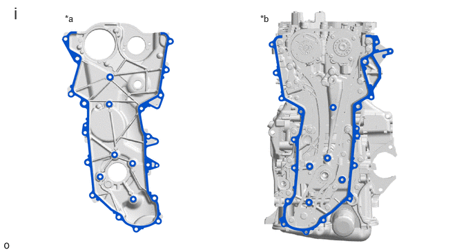
| *a | No. 2 Timing Chain Cover Assembly Side | *b | Timing Chain Cover Assembly Side |
Clean the contact surfaces of the No. 2 timing chain cover assembly and timing chain cover assembly, and confirm that no oil, moisture, or other foreign matter is on the surfaces.
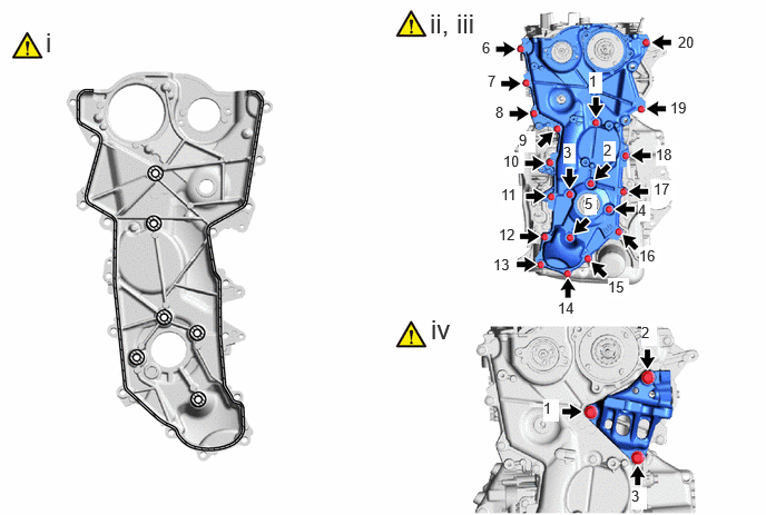
|
|
Seal Packing | - | - |
Apply seal packing in a continuous line to the No. 2 timing chain cover assembly as shown in the illustration.
- Seal Packing:
Toyota Genuine Seal Packing Black, Three Bond 1207B or equivalent
- Standard Seal Packing Diameter:
2.5 to 3.5 mm (0.0984 to 0.138 in.)
- NOTICE:
- ·
Clean the surfaces with non-residue solvent before applying seal packing.
·Install the No. 2 timing chain cover assembly within 3 minutes and tighten the bolts within 10 minutes of applying seal packing.
·Do not add engine oil for at least 2 hours after installation.
·Do not start the engine for at least 2 hours after installation.
·Make sure that the diameter at the start and end of each line of seal packing is 5 +/- 2 mm (0.197 +/- 0.0787 in.).
Temporarily install the No. 2 timing chain cover assembly to the timing chain cover assembly with the 20 bolts.
- NOTICE:
-
Make sure there is no oil on the bolts. If oil is found on any bolt, clean it before installation.
Tighten the 20 bolts in the order shown in the illustration.
- Torque:
- 24 N*m (245 kgf*cm, 18 ft.*lbf)
Install the engine mounting bracket RH with the 3 bolts in the order shown in the illustration.
- Torque:
- 43 N*m (438 kgf*cm, 32 ft.*lbf)
- NOTICE:
-
After applying seal packing to the No. 2 timing chain cover assembly, install the engine mounting bracket RH within 10 minutes.
39.INSTALL STRAIGHT SCREW PLUG
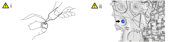
Apply adhesive to the straight screw plug.
- Adhesive:
Toyota Genuine Adhesive 1324, Three Bond 1324 or equivalent
Using a 10 mm hexagon wrench, install the straight screw plug to the No. 2 timing chain cover assembly.
- Torque:
- 40 N*m (408 kgf*cm, 30 ft.*lbf)
- NOTICE:
- ·
Install the straight screw plug within 3 minutes of applying adhesive.
·Do not add engine oil for at least 1 hour after installation.
11301C
40.INSTALL TIMING CHAIN COVER OIL SEAL
11193
41.INSTALL SPARK PLUG TUBE GASKET
11201
42.INSTALL CYLINDER HEAD COVER SUB-ASSEMBLY
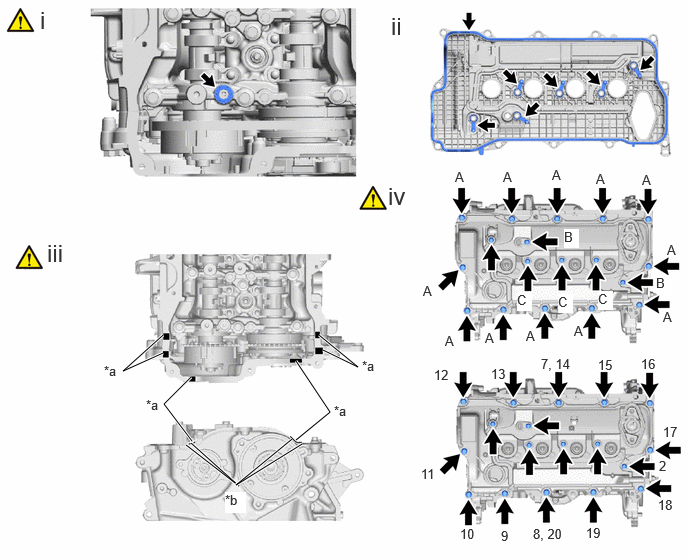
| *a | Seal Packing Diameter: 3.0 to 6.0 mm (0.118 to 0.236 in.) | *b | Mark |

|
Seal Packing | - | - |
Install a new camshaft bearing cap oil hole gasket to the No. 1 camshaft bearing cap.
- NOTICE:
-
Remove any oil from the contact surfaces.
Install 7 new cylinder head cover gaskets to the cylinder head cover sub-assembly.
- NOTICE:
-
Remove any oil from the contact surfaces.
Apply seal packing as shown in the illustration.
- Seal Packing:
Toyota Genuine Seal Packing Black, Three Bond 1207B or equivalent
- Standard Seal Packing Diameter:
3.0 to 6.0 mm (0.118 to 0.236 in.)
- NOTICE:
- ·
Remove any oil from the contact surfaces.
·Install the cylinder head cover sub-assembly within 3 minutes and tighten the bolts within 15 minutes of applying seal packing.
·Do not start the engine for at least 2 hours after installation.
Install the cylinder head cover sub-assembly with the 12 bolts (A) and using an 8 mm socket wrench, install 4 new bolts (C) and the 2 camshaft position sensors (for Exhaust Side and for Intake Side) with 2 new bolts (B) in the order shown in the illustration.
- Bolt Length:
Bolt Length Width Across Flats (A) 23.5 mm (0.925 in.) 10 mm (0.394 in.) (B), (C) 30 mm (1.18 in.) 8 mm (0.315 in.)
- Torque:
- 7.5 N*m (76 kgf*cm, 66 in.*lbf)
- NOTICE:
- ·
If a camshaft position sensor (for Exhaust Side and for Intake Side) has been struck or dropped, replace it.
·Make sure that the 2 O-rings are not cracked or moved out of place when installing the 2 camshaft position sensors (for Exhaust Side and for Intake Side).
·Do not start the engine for at least 2 hours after installation.
- HINT:
-
After tightening all bolts, check the tightening torque of the bolts (7) and (8). Retighten them if necessary.
16351
43.INSTALL WATER BY-PASS OUTLET
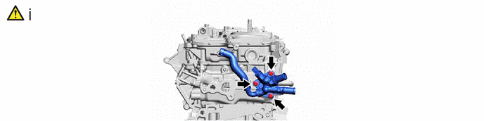
Using an 8 mm socket wrench, install the water by-pass outlet and a new water pipe outlet gasket to the cylinder head sub-assembly with the 3 bolts.
- Torque:
- 10 N*m (102 kgf*cm, 7 ft.*lbf)
16304
44.INSTALL WATER OUTLET SUB-ASSEMBLY
45.INSTALL OUTLET HEATER WATER HOSE
46.INSTALL INLET HEATER WATER HOSE
13470
47.INSTALL CRANKSHAFT PULLEY ASSEMBLY
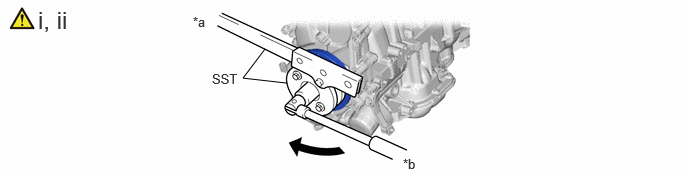
| *a | Hold | *b | Turn |
Align the crankshaft timing gear key with the key groove of the crankshaft pulley assembly.
Using SST, hold the crankshaft pulley assembly and install the crankshaft pulley bolt.
- SST
- 09213-54015
09330-00021
- Torque:
- 260 N*m (2651 kgf*cm, 192 ft.*lbf)
12204C
48.INSTALL PCV VALVE (VENTILATION VALVE SUB-ASSEMBLY)
11401G
49.INSTALL CRANKSHAFT POSITION SENSOR
12108A
50.INSTALL OIL FILLER CAP GASKET
12180E
51.INSTALL OIL FILLER CAP ASSEMBLY
13090E
52.INSTALL CAM TIMING CONTROL MOTOR O-RING
13090D
53.INSTALL CAM TIMING CONTROL MOTOR WITH EDU ASSEMBLY
15370
54.INSTALL CAM TIMING OIL CONTROL SOLENOID ASSEMBLY
11102A
55.INSTALL CAMSHAFT POSITION SENSOR (for Exhaust Side)
11102A
56.INSTALL CAMSHAFT POSITION SENSOR (for Intake Side)
15250
57.INSTALL OIL PRESSURE CONTROL VALVE ASSEMBLY
89448D
58.INSTALL OIL PRESSURE AND TEMPERATURE SENSOR
89615
59.INSTALL KNOCK CONTROL SENSOR
19100P
60.INSTALL SPARK PLUG