HYBRID / BATTERY CONTROL INVERTER WITH CONVERTER REASSEMBLY
CAUTION / NOTICE / HINT
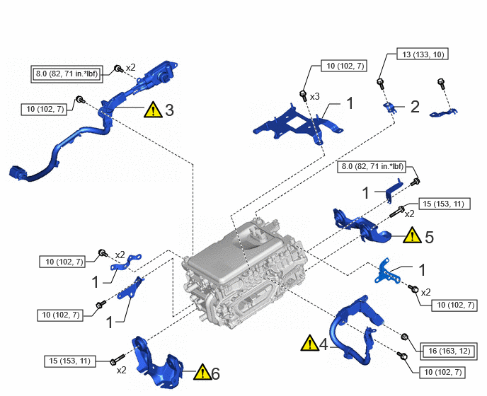
| Procedure | Part Name Code | 
|

|

|
|
|---|---|---|---|---|---|
| 1 | WIRE HARNESS CLAMP BRACKET | - | - | - | - |
| 2 | BRACKET | 23211K | - | - | - |
| 3 | HIGH VOLTAGE AIR CONDITIONING WIRE | 821H2A | ( 202307,999999,_51,_144957,_0604245,RM100000002BTRH_01_0004,) 202307,999999,_51,_144957,_0604245,RM100000002BTRH_01_0004,)
|
- | - |
| 4 | NO. 3 ENGINE WIRE | 82123 | (202307,999999,_51,_144957,_0604245,RM100000002BTRH_01_0003,)
|
- | - |
| 5 | NO. 2 INVERTER BRACKET | G9215 | (202307,999999,_51,_144957,_0604245,RM100000002BTRH_01_0002,)
|
- | - |
| 6 | NO. 1 INVERTER BRACKET | G9214 | (202307,999999,_51,_144957,_0604245,RM100000002BTRH_01_0001,)
|
- | - |

|
Tightening torque for "Major areas involving basic vehicle performance such as moving/turning/stopping" : N*m (kgf*cm, ft.*lbf) | 
|
N*m (kgf*cm, ft.*lbf): Specified torque |
PROCEDURE

 1.INSTALL WIRE HARNESS CLAMP BRACKET
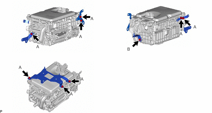
- Torque:
- Bolt A : 10 N*m (102 kgf*cm, 7 ft.*lbf)
- Bolt B : 8.0 N*m (82 kgf*cm, 71 in.*lbf)
23211K
2.INSTALL BRACKET
- Torque:
- 13 N*m (133 kgf*cm, 10 ft.*lbf)
821H2A
3.INSTALL HIGH VOLTAGE AIR CONDITIONING WIRE
|
|
|
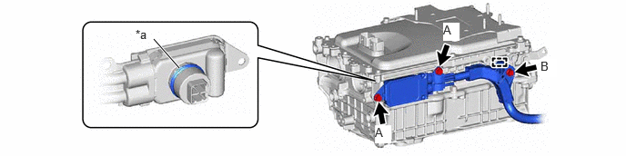
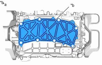
| *a | Waterproof Seal | - | - |
- Torque:
- Bolt A : 8.0 N*m (82 kgf*cm, 71 in.*lbf)
- Bolt B : 10 N*m (102 kgf*cm, 7 ft.*lbf)
82123
4.INSTALL NO. 3 ENGINE WIRE
|
|
|
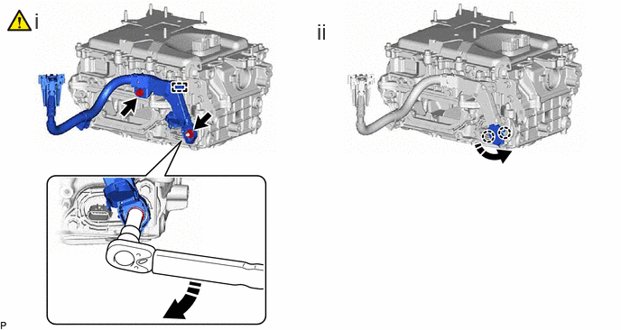
Engage the clamp and connect the engine wire to the inverter with converter assembly with bolt and nut.
- Torque:
- Bolt : 10 N*m (102 kgf*cm, 7 ft.*lbf)
- Nut : 16 N*m (163 kgf*cm, 12 ft.*lbf)
- NOTICE:
- ·
Move the tool in the downward direction to tighten the nut as shown in the illustration.
·To avoid damaging the threads, be sure to perform the procedure by hand.
Engage the 2 claws.
G9215
5.INSTALL NO. 2 INVERTER BRACKET
|
|
|
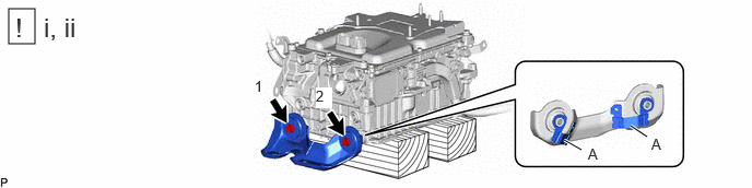
Set the inverter with converter assembly on wooden blocks.
Temporarily install the No. 2 inverter bracket to the inverter with converter assembly with the 2 bolts.
- NOTICE:
-
Do not touch portion (A) of the No. 2 inverter bracket.
Fully tighten the 2 bolts in the order shown in the illustration.
- Torque:
- 15 N*m (153 kgf*cm, 11 ft.*lbf)
G9214
6.INSTALL NO. 1 INVERTER BRACKET
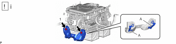
Temporarily install the No. 1 inverter bracket to the inverter with converter assembly with the 2 bolts.
- NOTICE:
-
Do not touch portion (A) of the No. 1 inverter bracket.
Fully tighten the 2 bolts in the order shown in the illustration.
- Torque:
- 15 N*m (153 kgf*cm, 11 ft.*lbf)