HYBRID / BATTERY CONTROL HYBRID CONTROL SYSTEM P056014 System Voltage (BATT) Circuit Short to Ground or Open
DESCRIPTION
Auxiliary battery power is supplied to the BATT terminal of the hybrid vehicle control ECU in order to store DTCs and freeze frame data. Even if the ignition switch is turned off, back-up power is supplied.
| DTC No. | Detection Item | DTC Detection Condition | Trouble Area | MIL | Warning Indicate | Note |
|---|---|---|---|---|---|---|
| P056014 | System Voltage (BATT) Circuit Short to Ground or Open | Malfunction in the hybrid vehicle control ECU back-up power source circuit
(1 trip detection logic) |
·
Wire harness or connector ·
Hybrid vehicle control ECU ·
Fuse |
Comes on | Master Warning:
Comes on |
SAE Code:
P0562 |
MONITOR DESCRIPTION
If a period of time has elapsed with a low voltage at the BATT terminal of the hybrid vehicle control ECU, the hybrid vehicle control ECU will determine that a malfunction has occurred in the back-up power supply system, and it will store a DTC. The MIL will illuminate the next time the ignition switch ON.
MONITOR STRATEGY
| Related DTCs | P0562 (INF P056014): System voltage range check (Low voltage) |
| Required sensors/components | Main: Back-up power source circuit
Sub: Hybrid vehicle control ECU |
| Frequency of operation | Continuous |
| Duration | TMC's intellectual property |
| MIL operation | Immediately |
| Sequence of operation | None |
TYPICAL ENABLING CONDITIONS
| The monitor will run whenever the following DTCs are not stored | TMC's intellectual property |
| Other conditions belong to TMC's intellectual property | - |
TYPICAL MALFUNCTION THRESHOLDS
| TMC's intellectual property | - |
COMPONENT OPERATING RANGE
| Auxiliary battery voltage | Between 9 and 14 V |
CONFIRMATION DRIVING PATTERN
- HINT:
- ·
After repair has been completed, clear the DTC and then check that the vehicle has returned to normal by performing the following All Readiness check procedure.
·When clearing the permanent DTCs, refer to the "CLEAR PERMANENT DTC" procedure.
Connect the GTS to the DLC3.
Turn the ignition switch to ON and turn the GTS on.
Clear the DTCs (even if no DTCs are stored, perform the clear DTC procedure).
Turn the ignition switch off and wait for 2 minutes or more.
Turn the ignition switch to ON and turn the GTS on.
With ignition switch ON and wait for 5 seconds or more. [*1]
- HINT:
-
[*1]: Normal judgment procedure.
-
The normal judgment procedure is used to complete DTC judgment and also used when clearing permanent DTCs.
Enter the following menus: Powertrain / Hybrid Control / Utility / All Readiness.
Check the DTC judgment result.
- HINT:
- ·
If the judgment result shows NORMAL, the system is normal.
·If the judgment result shows ABNORMAL, the system has a malfunction.
·If the judgment result shows INCOMPLETE, perform the normal judgment procedure again.
WIRING DIAGRAM
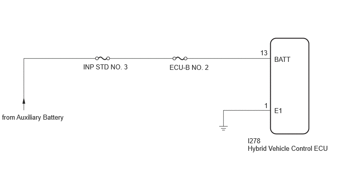
CAUTION / NOTICE / HINT
- NOTICE:
- ·
Be sure to check that the applicable DTC is output from the hybrid control system.
·After the ignition switch is turned off, there may be a waiting time before disconnecting the negative (-) auxiliary battery terminal.
·When disconnecting and reconnecting the auxiliary battery
- HINT:
-
When disconnecting and reconnecting the auxiliary battery, there is an automatic learning function that completes learning when the respective system is used.
PROCEDURE
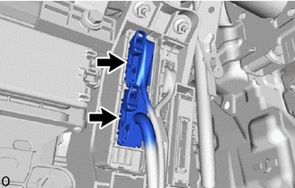
Check the connector connections and contact pressure of the relevant terminals for the hybrid vehicle control ECU connectors.
- OK:
The connectors are connected securely and there are no contact pressure problems.
- Result:
Proceed to OK NG
OK
NG
Turn the ignition switch off.
Measure the voltage according to the value(s) in the table below.
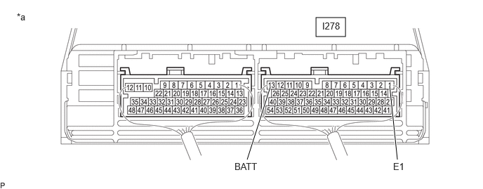
| *a | Component with harness connected
(Hybrid Vehicle Control ECU) |
- | - |
- Standard Voltage:
Tester Connection Condition Specified Condition I278-13 (BATT) - I278-1 (E1) Ignition switch off 11 to 14 V
- Result:
Proceed to OK NG
OK
NG
Remove the ECU-B NO. 2 fuse from the power distribution box assembly.
Check if there is an open circuit in the ECU-B NO. 2 fuse in the power distribution box assembly.
- OK:
There is no open circuit in the ECU-B NO. 2 fuse.
Install the ECU-B NO. 2 fuse.
- Result:
Proceed to OK NG
OK
NG