HYBRID / BATTERY CONTROL HYBRID CONTROL SYSTEM P253012 IG2 Signal Circuit Short to Auxiliary Battery
DESCRIPTION
The hybrid vehicle control ECU compares the IGP signal to the IG control status signal sent from the certification ECU (smart key ECU assembly) to detect a stuck on malfunction of the IGP signal.
- HINT:
-
If DTC P253012 is stored, the ignition switch will turn off (READY off).
| DTC No. | Detection Item | DTC Detection Condition | Trouble Area | MIL | Warning Indicate | Note |
|---|---|---|---|---|---|---|
| P253012 | IG2 Signal Circuit Short to Auxiliary Battery | The IGP signal of the hybrid vehicle control ECU and the IG switch signal sent from the certification ECU (smart key ECU assembly) do not match.
(1 trip detection logic) |
·
Auxiliary battery ·
Certification ECU (smart key ECU assembly) ·
Hybrid vehicle control ECU ·
ECM ·
IGP-MAIN relay ·
Wire harness or connector |
Does not come on | Master Warning:
Comes on |
SAE Code:
P2532 |
CONFIRMATION DRIVING PATTERN
- HINT:
-
After repair has been completed, clear the DTCs and then check that the vehicle has returned to normal by performing the following All Readiness check procedure.
Connect the GTS to the DLC3.
Turn the ignition switch to ON and turn the GTS on.
Clear the DTCs (even if no DTCs are stored, perform the clear DTC procedure).
Turn the ignition switch off and wait for 2 minutes or more.
Turn the ignition switch to ON and wait for 15 seconds or more.
Turn the ignition switch off and wait for 2 minutes or more.
Turn the ignition switch to ON and turn the GTS on.
Enter the following menus: Powertrain / Hybrid Control / Utility / All Readiness.
Check the DTC judgment result.
- HINT:
- ·
If the judgment result shows NORMAL, the system is normal.
·If the judgment result shows ABNORMAL, the system has a malfunction.
·If the judgment result shows INCOMPLETE, perform driving pattern again.
WIRING DIAGRAM
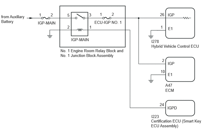
CAUTION / NOTICE / HINT
- NOTICE:
-
Before replacing the certification ECU (smart key ECU assembly), refer to Service Bulletin.
PROCEDURE
Turn the ignition switch off and turn on the high beam headlights for 30 seconds. This will remove the surface charge from the auxiliary battery.
Measure the auxiliary battery voltage according to the value(s) in the table below.
- Standard Voltage:
Tester Connection Condition Specified Condition Positive (+) auxiliary battery terminal - Negative (-) auxiliary battery terminal 20°C (68°F), Ignition switch off 11.0 V or higher
- Result:
Proceed to OK NG
OK
NG
Charge or replace the auxiliary battery.
- Result:
Proceed to NEXT
NEXT
Clear the DTCs.
- Powertrain > Hybrid Control > Clear DTCs
- 50002 397
Turn the ignition switch off.
- Result:
Proceed to NEXT
NEXT
Turn the ignition switch to ON and wait for 15 seconds or more.
Turn the ignition switch off and wait for 2 minutes or more.
Check for DTCs.
- Powertrain > Hybrid Control > Trouble Codes
- 50001 397
- Result:
Result Proceed to P253012 is output. A P253012 is not output. B
Turn the ignition switch off.
A
B
Check for DTCs.
- Powertrain > Hybrid Control > Trouble Codes
- 50001 397
- Result:
Result Proceed to U012987, U014087, U015187, U016487, U110787 or U117087 is output A Other than above B
Turn the ignition switch off.
A
B
Remove the IGP-MAIN relay from the No. 1 engine room relay block and No. 1 junction block assembly.
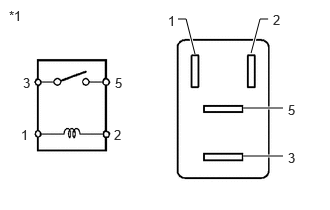
| *1 | IGP-MAIN Relay |
Measure the resistance according to the value(s) in the table below.
- Standard Resistance:
Tester Connection Condition Specified Condition 3 - 5 Auxiliary battery voltage not applied between terminals 1 and 2 10 kΩ or higher Auxiliary battery voltage applied between terminals 1 and 2 Below 1 Ω
Install the IGP-MAIN relay.
- Result:
Proceed to OK NG
OK
NG
Check for DTCs.
- Body Electrical > Main Body > Trouble Codes
- 50001 449
- Result:
Result Proceed to DTCs related to CXPI communication system are output. A Other than above B
Turn the ignition switch off.
A
B
Remove the IGP-MAIN relay from the No. 1 engine room relay block and No. 1 junction block assembly.
Measure the voltage according to the value(s) in the table below.
- Standard Voltage:
Tester Connection Condition Specified Condition 1 (IGP-MAIN relay holder) - Body ground Ignition switch off 1 V or less
Install the IGP-MAIN relay.
- Result:
Proceed to OK NG
OK
NG
Remove the IGP-MAIN relay from the No. 1 engine room relay block and No. 1 junction block assembly.
Measure the voltage according to the value(s) in the table below.
- Standard Voltage:
Tester Connection Condition Specified Condition 3 (IGP-MAIN relay holder) - Body ground Ignition switch off 1 V or less
Install the IGP-MAIN relay.
- Result:
Proceed to OK NG
OK
Check for intermittent problems.
Check the connection and terminal contact pressure of the connectors and wire harnesses between the hybrid vehicle control ECU and the IGP-MAIN relay.
When the ignition switch is ON (READY), jiggle the connectors and wire harnesses between the hybrid vehicle control ECU and the IGP-MAIN relay.
NG
Disconnect the certification ECU (smart key ECU assembly) connector.
Remove the IGP-MAIN relay from the No. 1 engine room relay block and No. 1 junction block assembly.
Measure the voltage according to the value(s) in the table below.
- Standard Voltage:
Tester Connection Condition Specified Condition 1 (IGP-MAIN relay holder) - Body ground Ignition switch off 1 V or less
Install the IGP-MAIN relay.
Reconnect the certification ECU (smart key ECU assembly) connector.
- Result:
Proceed to OK NG
OK
NG
Disconnect the hybrid vehicle control ECU connector.
Remove the IGP-MAIN relay from the No. 1 engine room relay block and No. 1 junction block assembly.
Measure the voltage according to the value(s) in the table below.
- Standard Voltage:
Tester Connection Condition Specified Condition 3 (IGP-MAIN relay holder) - Body ground Ignition switch off 1 V or less
Install the IGP-MAIN relay.
Reconnect the hybrid vehicle control ECU connector.
- Result:
Proceed to OK NG
OK
NG
Disconnect the ECM connector.
Remove the IGP-MAIN relay from the No. 1 engine room relay block and No. 1 junction block assembly.
Measure the voltage according to the value(s) in the table below.
- Standard Voltage:
Tester Connection Condition Specified Condition 3 (IGP-MAIN relay holder) - Body ground Ignition switch off 1 V or less
Install the IGP-MAIN relay.
Reconnect the ECM connector.
- Result:
Proceed to OK NG
OK
NG