M20F-FXS, M20G-FXS ENGINE CONTROL MASS AIR FLOW METER ON-VEHICLE INSPECTION
PROCEDURE

 22204
1.INSPECT MASS AIR FLOW METER SUB-ASSEMBLY
22204
1.INSPECT MASS AIR FLOW METER SUB-ASSEMBLY
- HINT:
-
Perform "Inspection After Repair" after replacing the mass air flow meter sub-assembly.
Read the value of Data List item "Mass Air Flow Sensor" using the GTS.
- NOTICE:
-
Perform the inspection of the mass air flow meter sub-assembly while it is installed to the air cleaner cap sub-assembly (installed to the vehicle).
Check and ensure the following conditions:
Turn off all electrical loads, such as the air conditioning, etc.
Check that the coolant temperature is 75°C (167°F) or more.
Put the shift lever in the N position.
Connect the GTS to the DLC3.
Turn the power switch on (IG).
Turn the GTS on.
Put the engine in Inspection Mode (Maintenance Mode).
- Powertrain > Hybrid Control > Utility
-
Tester Display Inspection Mode - 50005 397 2103
Start the engine.
Enter the following menus: Powertrain / Engine / Data List / Mass Air Flow Sensor.
- Powertrain > Engine > Data List
-
Tester Display Mass Air Flow Sensor - 50003 372 215
According to the display on the GTS, read the Data List when the engine is running.
- Standard Condition:
GTS Display Condition Specified Condition Mass Air Flow Sensor Idling (shift lever in N, engine warmed up, inspection mode [maintenance mode] and not charge control) 2.0 to 8.6 gm/sec 2500 rpm (shift lever in N, engine warmed up and inspection mode [maintenance mode] ) 5.5 to 18.6 gm/sec
If the result is not as specified, clean the mass air flow meter sub-assembly.
If the result is within the specified range, inspect the mass air flow meter sub-assembly.
22204
2.CLEAN MASS AIR FLOW METER SUB-ASSEMBLY
- NOTICE:
-
If the mass air flow meter sub-assembly is removed and installed 10 times or more, the thread of the hole of the mass air flow meter sub-assembly may be damaged. Therefore, do not loosen the screws of the mass air flow meter sub-assembly.
Remove the air cleaner cap sub-assembly.
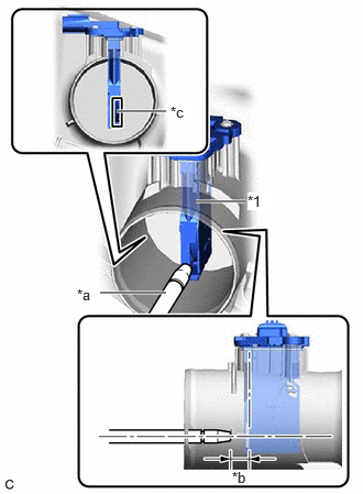
| *1 | Mass Air Flow Meter Sub-assembly |
| *a | Air Blow Gun |
| *b | 10 mm (0.394 in.) |
| *c | Airflow Hole |
Clean the mass air flow meter sub-assembly.
- NOTICE:
- ·
Do not contact the mass air flow meter sub-assembly with the nozzle of the air blow gun.
·Do not insert the nozzle of the air blow gun into the airflow hole.
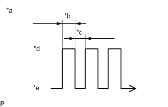
| *a | Air Blow Duration |
| *b | 3 to 6 Seconds |
| *c | 1 Second |
| *d | Air Blowing |
| *e | Air Stopped |
Using an air blow gun, clean the hole of the mass air flow meter sub-assembly by applying approximately 10 intermittent bursts of air to the airflow hole at a pressure of approximately 392 to 981 kPa (4.0 to 10.0 kgf/cm2, 57 to 142 psi).
Install the air cleaner cap sub-assembly.
3.PERFORM INITIALIZATION
Perform "Inspection After Repair" after replacing the mass air flow meter sub-assembly.