M20F-FXS, M20G-FXS ENGINE CONTROL THROTTLE BODY INSTALLATION
CAUTION / NOTICE / HINT
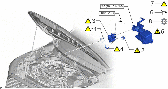
| Procedure | Part Name Code | 
|

|

|
|
|---|---|---|---|---|---|
| 1 | THROTTLE BODY GASKET | 22271 | ( 202307,999999,_51,_144956,_0604219,RM100000002BTIF_01_0032,) 202307,999999,_51,_144956,_0604219,RM100000002BTIF_01_0032,)
|
- | - |
| 2 | NO. 5 WATER BY-PASS HOSE | - | (202307,999999,_51,_144956,_0604219,RM100000002BTIF_01_0039,)
|
- | - |
| 3 | THROTTLE BODY WITH MOTOR ASSEMBLY | 22030 | (202307,999999,_51,_144956,_0604219,RM100000002BTIF_01_0033,)
|
- | - |
| 4 | NO. 8 WATER BY-PASS HOSE | 16296 | (202307,999999,_51,_144956,_0604219,RM100000002BTIF_01_0038,)
|
- | - |
| 5 | AIR CLEANER CAP WITH AIR CLEANER HOSE | - | (202307,999999,_51,_144956,_0604219,RM100000002BTIF_01_0034,)
|
- | - |
| 6 | ADD ENGINE COOLANT | - | - | (202307,999999,_51,_144956,_0604219,RM100000002BTIF_01_0035,)
|
- |
| 7 | INSPECT FOR COOLANT LEAK | - | (202307,999999,_51,_144956,_0604219,RM100000002BTIF_01_0036,)
|
- | - |
| 8 | PERFORM INITIALIZATION | - | - | - | (202307,999999,_51,_144956,_0604219,RM100000002BTIF_01_0037,)
|

|
N*m (kgf*cm, ft.*lbf): Specified torque | ● | Non-reusable part |
CAUTION / NOTICE / HINT
- NOTICE:
-
This procedure includes the installation of small-head bolts. Refer to Small-Head Bolts of Basic Repair Hint to identify the small-head bolts.
PROCEDURE

 22271
1.INSTALL THROTTLE BODY GASKET
22271
1.INSTALL THROTTLE BODY GASKET

| *a | Protrusion | - | - |
Install a new throttle body gasket to the intake manifold with the protrusion of the throttle body gasket oriented as shown in the illustration.
2.INSTALL NO. 5 WATER BY-PASS HOSE
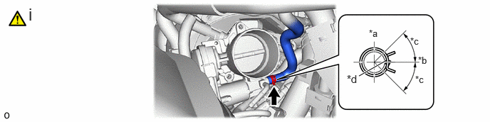
| *a | Top of Vehicle | *b | Left of Vehicle |
| *c | 45°(Claw of Clip Location) | *d | Paint Mark |
Connect the No. 5 water by-pass hose to the throttle body with motor assembly and slide the clip to secure it.
- NOTICE:
- ·
If the throttle body with motor assembly has been struck or dropped, replace it.
·Make sure to position the clip as shown in the illustration.
22030
3.INSTALL THROTTLE BODY WITH MOTOR ASSEMBLY
|
|
|
- Torque:
- 10 N*m (102 kgf*cm, 7 ft.*lbf)
16296
4.CONNECT NO. 8 WATER BY-PASS HOSE
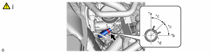
| *a | Top of Vehicle | *b | Left of Vehicle |
| *c | 45°(Claw of Clip Location) | *d | Paint Mark |
Connect the No. 8 water by-pass hose to the throttle body with motor assembly and slide the clip to secure it.
- NOTICE:
-
Make sure to position the clip as shown in the illustration.
5.INSTALL AIR CLEANER CAP WITH AIR CLEANER HOSE

| *1 | No. 2 Ventilation Hose | - | - |
| *a | Protrusion | *b | Cutout |
| *c | Top of Vehicle | *d | Front of Vehicle |
| *e | 45°(Claw of Clip Location) | - | - |
Install the air cleaner cap with air cleaner hose to the throttle body with motor assembly and tighten the hose clamp.
- Torque:
- 2.0 N*m (20 kgf*cm, 18 in.*lbf)
- NOTICE:
-
Align the cutout of the air cleaner hose with the protrusion of the throttle body with motor assembly as shown in the illustration.
Connect the No. 2 ventilation hose to the cylinder head cover sub-assembly and slide the clip to secure it.
- NOTICE:
-
Make sure to position the clip as shown in the illustration.
Engage the 2 guides and 2 clamps.
Engage the wire harness clamp and connect the mass air flow meter connector.
6.ADD ENGINE COOLANT
7.INSPECT FOR COOLANT LEAK
8.PERFORM INITIALIZATION
- NOTICE:
- ·
Be sure to perform this procedure after removing and reinstalling the throttle body with motor assembly or any throttle body with motor assembly components.
·Perform the following procedure after replacing the throttle body with motor assembly or any throttle body with motor assembly components. The following procedure should also be performed if the throttle body with motor assembly is cleaned.
Connect the GTS to the DLC3.
Turn the ignition switch to ON.
Turn the GTS on.
Clear the DTCs.
- Powertrain > Engine > Clear DTCs
- 50002 372
Perform "Inspection After Repair".
Start the engine and check that the MIL is not illuminated. After the engine is warmed up, check that the idle speed is within the specified range with the A/C switch off.
- Standard Idle Speed:
750 to 850 rpm
- NOTICE:
- ·
Be sure to perform this step with all accessories off.
·Make sure that the shift lever is in P or N.
Enter the following menus: Powertrain / Engine / Data List / Throttle Position Sensor No.1 Voltage %.
- Powertrain > Engine > Data List
-
Tester Display Throttle Position Sensor No.1 Voltage % - 50003 372 216
According to the display on the GTS, read the Data List while fully depressing the accelerator pedal and check that the value is 60% or higher.
Perform a road test and confirm that there are no abnormalities.