ADVANCED DRIVER ASSISTANCE SYSTEM FRONT CAMERA SYSTEM(Production Date from 2023/04) TERMINALS OF ECU
CHECK FORWARD RECOGNITION CAMERA
- NOTICE:
- ·
DTCs may be output when connectors are disconnected during inspection. Therefore, be sure to clear the DTCs using the GTS once the inspection has been completed.
·Do not apply excessive force to the forward recognition camera connector.

Measure the voltage and resistance according to the value(s) in the table below.
| Terminal No. (Symbol) | Terminal Description | Condition | Specified Condition |
|---|---|---|---|
| T37-1 (CA2L) | CAN communication signal | - | - |
| T37-2 (CA2P) | CAN communication signal | - | - |
| T37-5 (LKSW) - T37-13 (GND) | Driving assist mode select switch, LTA switch and Vehicle-to-vehicle distance switch circuit | Driving assist mode select switch, LTA switch and Vehicle-to-vehicle distance switch OFF | 10 kΩ or higher |
| Driving assist mode select switch pushed | Below 2.5 Ω | ||
| LTA switch pushed | 114 to 126 Ω | ||
| Vehicle-to-vehicle distance switch pushed | 485 to 536 Ω | ||
| T37-8 (HTR) - T37-7 (SGND) | Camera heater circuit | Ignition switch ON, heater operating | 11 to 14 V |
| Ignition switch ON, heater not operating | Below 1 V | ||
| T37-9 (CA1N) | CAN communication signal | - | - |
| T37-10 (CA1P) | CAN communication signal | - | - |
| T37-11 (CANL) | CAN communication signal | - | - |
| T37-12 (CANH) | CAN communication signal | - | - |
| T37-16 (IGB) - T37-13 (GND) | Power source (IG) | Ignition switch ON | 11 to 14 V |
| Ignition switch off | Below 1 V |
CHECK ECM (for Gasoline Model)
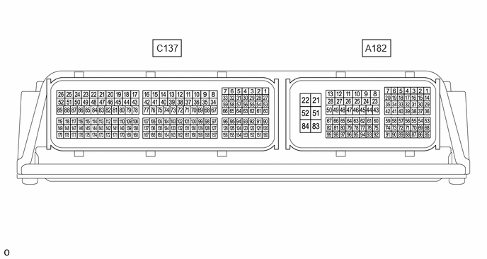
- HINT:
-
The standard voltage, resistance and waveform between each pair of the ECM terminals is shown in the table below. The appropriate conditions for checking each pair of the terminals is also indicated. The result of checks should be compared with the standard voltage, resistance and waveform for each pair of the terminals as displayed in the Specified Condition column. The illustration above can be used as a reference to identify the ECM terminal locations.
Measure the resistance according to the value(s) in the table below.
| Terminal No. (Symbols) | Terminal Description | Condition | Specified Condition |
|---|---|---|---|
| A182-91 (CCS) - A182-92 (ECCS) | Driving assist switch, +RES switch, - switch, CANCEL switch circuit | Driving assist switch, +RES switch, - switch, CANCEL switch OFF | 10 kΩ or higher |
| Driving assist switch pushed | Below 2.5 Ω | ||
| CANCEL switch pushed | 228 to 252 Ω | ||
| +RES switch pushed | 599 to 661 Ω | ||
| - switch pushed | 1463 to 1617 Ω |
CHECK HYBRID VEHICLE CONTROL ECU (for HEV Model)
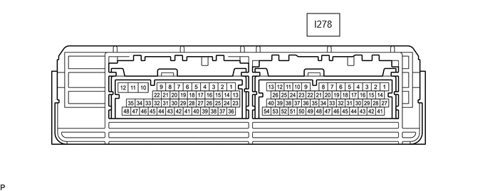
Measure the resistance according to the value(s) in the table below.
| Terminal No. (Symbols) | Terminal Description | Condition | Specified Condition |
|---|---|---|---|
| I278-29 (CCS) - I278-43 (CCSG) | Driving assist switch, +RES switch, - switch, CANCEL switch circuit | Driving assist switch, +RES switch, - switch, CANCEL switch OFF | 10 kΩ or higher |
| Driving assist switch pushed | Below 2.5 Ω | ||
| CANCEL switch pushed | 228 to 252 Ω | ||
| +RES switch pushed | 599 to 661 Ω | ||
| - switch pushed | 1463 to 1617 Ω |