PB10 HYBRID TRANSMISSION / TRANSAXLE OIL COOLER INSTALLATION
CAUTION / NOTICE / HINT
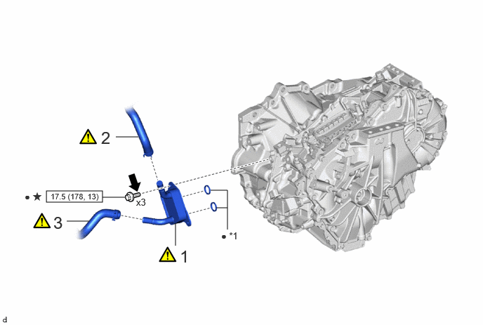
| Procedure | Part Name Code | 
|

|

|
|
|---|---|---|---|---|---|
| 1 | MOTOR COOLING COOLER | G125AA | ( 202307,999999,_52,_144756,_0603120,RM100000002BO7Z_01_0014,) 202307,999999,_52,_144756,_0603120,RM100000002BO7Z_01_0014,)
|
- | - |
| 2 | OUTLET NO. 1 INVERTER COOLING HOSE | G922C | (202307,999999,_52,_144756,_0603120,RM100000002BO7Z_01_0012,)
|
- | - |
| 3 | OUTLET NO. 2 INVERTER COOLING HOSE | G922D | (202307,999999,_52,_144756,_0603120,RM100000002BO7Z_01_0013,)
|
- | - |
| *1 | TRANSAXLE OIL SEAL RING | - | - |

|
N*m (kgf*cm, ft.*lbf): Specified torque | ● | Non-reusable part |

|
Toyota Genuine Adhesive 1324, Three Bond 1324 or equivalent | ★ | Precoated part |
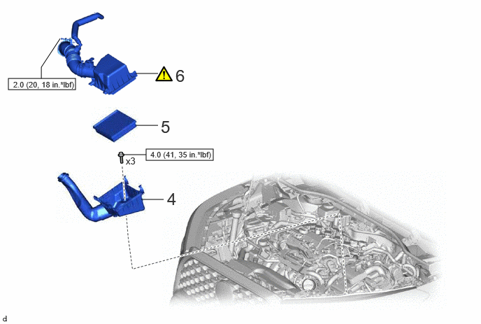
| Procedure | Part Name Code |
|
|
|
|
|---|---|---|---|---|---|
| 4 | AIR CLEANER CASE SUB-ASSEMBLY | 17701 | - | - | - |
| 5 | AIR CLEANER FILTER ELEMENT SUB-ASSEMBLY | 17801 | - | - | - |
| 6 | AIR CLEANER CAP WITH AIR CLEANER HOSE | - | (202307,999999,_52,_144756,_0603120,RM100000002BO7Z_01_0027,)
|
- | - |
|
|
N*m (kgf*cm, ft.*lbf): Specified torque | - | - |
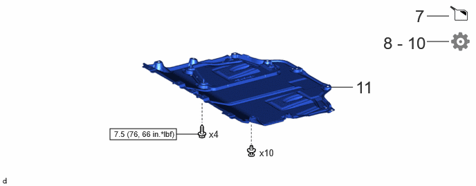
| Procedure | Part Name Code |
|
|
|
|
|---|---|---|---|---|---|
| 7 | ADD COOLANT (for Inverter) | - | - | (202307,999999,_52,_144756,_0603120,RM100000002BO7Z_01_0026,)
|
- |
| 8 | INSPECT HYBRID TRANSAXLE FLUID | - | - | - | (202307,999999,_52,_144756,_0603120,RM100000002BO7Z_01_0023,)
|
| 9 | INSPECT FOR COOLANT LEAK (for Inverter) | - | - | - | (202307,999999,_52,_144756,_0603120,RM100000002BO7Z_01_0025,)
|
| 10 | INSPECT FOR HYBRID TRANSAXLE FLUID LEAK | - | - | - | (202307,999999,_52,_144756,_0603120,RM100000002BO7Z_01_0024,)
|
| 11 | NO. 1 ENGINE UNDER COVER ASSEMBLY | 51410 | - | - | - |
|
|
N*m (kgf*cm, ft.*lbf): Specified torque | - | - |
PROCEDURE

 G125AA
1.INSTALL MOTOR COOLING COOLER
G125AA
1.INSTALL MOTOR COOLING COOLER
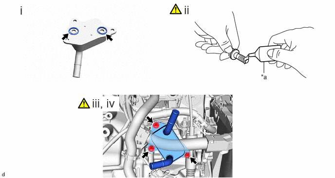
| *a | Adhesive | - | - |
Install 2 new transaxle oil seal rings to the motor cooling cooler.
Apply adhesive to 3 new bolts.
- Adhesive:
Toyota Genuine Adhesive 1324, Three Bond 1324 or equivalent
Temporarily install the motor cooling cooler to the hybrid vehicle transaxle assembly with the 3 bolts.
- NOTICE:
-
Make sure that the transaxle oil seal rings are not pinched during installation.
Fully tighten the 3 bolts.
- Torque:
- 17.5 N*m (178 kgf*cm, 13 ft.*lbf)
G922C
2.CONNECT OUTLET NO. 1 INVERTER COOLING HOSE
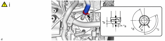
| *a | Paint Mark | *b | 2 to 11 mm (0.0787 to 0.433 in.) |
| *c | 115° | *d | 275° (Claw of Clip Location) |
Connect the outlet No. 1 inverter cooling hose to the motor cooling cooler and slide the clip to secure it.
- NOTICE:
- ·
Make sure to slide the outlet No. 1 inverter cooling hose until it contacts the hose stopper of the motor cooling cooler.
·Make sure to align the paint mark of the outlet No. 1 inverter cooling hose with the paint mark of the motor cooling cooler.
·Make sure that the claws of the clip are within the location shown in the illustration.
G922D
3.CONNECT OUTLET NO. 2 INVERTER COOLING HOSE

| *a | Paint Mark | *b | 2 to 11 mm (0.0787 to 0.433 in.) |
| *c | 360° (Claw of Clip Location) | - | - |
Connect the outlet No. 2 inverter cooling hose to the motor cooling cooler and slide the clip to secure it.
- NOTICE:
- ·
Make sure to slide the outlet No. 2 inverter cooling hose until it contacts the hose stopper of the motor cooling cooler.
·Make sure to align the paint mark of the outlet No. 2 inverter cooling hose with the paint mark of the motor cooling cooler.
·Make sure that the claws of the clip are within the location shown in the illustration.
17701
4.INSTALL AIR CLEANER CASE SUB-ASSEMBLY
17801
5.INSTALL AIR CLEANER FILTER ELEMENT SUB-ASSEMBLY
6.INSTALL AIR CLEANER CAP WITH AIR CLEANER HOSE
7.ADD COOLANT (for Inverter)
8.INSPECT HYBRID TRANSAXLE FLUID
9.INSPECT FOR COOLANT LEAK (for Inverter)
10.INSPECT FOR HYBRID TRANSAXLE FLUID LEAK
51410
11.INSTALL NO. 1 ENGINE UNDER COVER ASSEMBLY