M20F-FXS, M20G-FXS COOLING WATER PUMP INSTALLATION
CAUTION / NOTICE / HINT
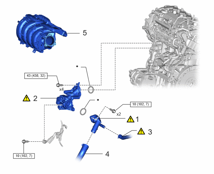
| Procedure | Part Name Code | 
|

|

|
|
|---|---|---|---|---|---|
| 1 | WATER INLET SUB-ASSEMBLY WITH THERMOSTAT | 16031 | ( 202307,999999,_51,_144716,_0602998,RM100000002BNM7_01_0040,) 202307,999999,_51,_144716,_0602998,RM100000002BNM7_01_0040,)
|
- | - |
| 2 | ENGINE WATER PUMP ASSEMBLY (WATER INLET HOUSING) | 16032 | (202307,999999,_51,_144716,_0602998,RM100000002BNM7_01_0005,)
|
- | - |
| 3 | NO. 7 WATER BY-PASS HOSE | - | (202307,999999,_51,_144716,_0602998,RM100000002BNM7_01_0039,)
|
- | - |
| 4 | NO. 2 RADIATOR HOSE | 16572D | - | - | - |
| 5 | INTAKE MANIFOLD | 17111 | - | - | - |

|
N*m (kgf*cm, ft.*lbf): Specified torque | ● | Non-reusable part |
| Procedure | Part Name Code |
|
|
|
|
|---|---|---|---|---|---|
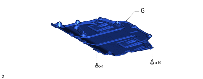
| 6 | NO. 1 ENGINE UNDER COVER ASSEMBLY | 51410 | - | - | - |
CAUTION / NOTICE / HINT
- NOTICE:
-
This procedure includes the installation of small-head bolts. Refer to Small-Head Bolts of Basic Repair Hint to identify the small-head bolts.
PROCEDURE

 16031
1.INSTALL WATER INLET SUB-ASSEMBLY WITH THERMOSTAT
16031
1.INSTALL WATER INLET SUB-ASSEMBLY WITH THERMOSTAT
16032
2.INSTALL ENGINE WATER PUMP ASSEMBLY (WATER INLET HOUSING)
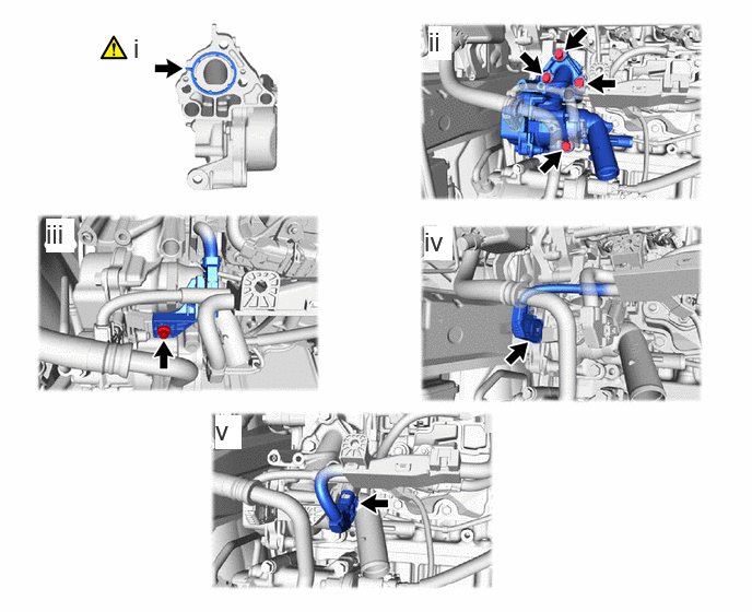
Install a new gasket to the engine water pump assembly (water inlet housing).
- HINT:
-
Be sure to clean the contact surfaces.
Install the engine water pump assembly (water inlet housing) to the cylinder block assembly with the 4 bolts.
- Torque:
- 43 N*m (438 kgf*cm, 32 ft.*lbf)
Using an 8 mm socket wrench, connect the sensor wire to the engine water pump assembly (water inlet housing) with the bolt.
- Torque:
- 10 N*m (102 kgf*cm, 7 ft.*lbf)
Connect the engine water pump assembly (water inlet housing) connector.
Connect the sensor wire connector.
3.CONNECT NO. 7 WATER BY-PASS HOSE

| *a | 15° | *b | 90° |
| *c | Upper Side | *d | Front Side |
| *e | 1 to 7 mm (0.0394 to 0.276 in.) | - | - |
Connect the No. 7 water by-pass hose to the water inlet with thermostat sub-assembly and slide the clip to secure it.
16572D
4.CONNECT NO. 2 RADIATOR HOSE
17111
5.INSTALL INTAKE MANIFOLD
51410
6.INSTALL NO. 1 ENGINE UNDER COVER ASSEMBLY