HEATING / AIR CONDITIONING AIR CONDITIONING UNIT REASSEMBLY
CAUTION / NOTICE / HINT
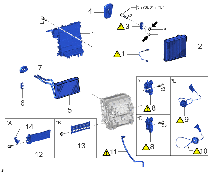
| Procedure | Part Name Code | 
|

|

|
|
|---|---|---|---|---|---|
| 1 | NO. 1 COOLER THERMISTOR | 88625 | ( 202307,999999,_58,_104612,_0500007,RM100000002BK0Z_01_0083,) 202307,999999,_58,_104612,_0500007,RM100000002BK0Z_01_0083,)
|
- | - |
| 2 | NO. 1 COOLER EVAPORATOR SUB-ASSEMBLY | 88501 | - | - | - |
| 3 | COOLER EXPANSION VALVE | 88515 | (202307,999999,_58,_104612,_0500007,RM100000002BK0Z_01_0076,)
|
- | - |
| 4 | COOLER PIPE GROMMET | 88897K | - | - | - |
| 5 | HEATER RADIATOR UNIT SUB-ASSEMBLY | 87107A | - | - | - |
| 6 | HEATER CLAMP | 87124B | - | - | - |
| 7 | HEATER GROMMET | 87128 | - | - | - |
| 8 | NO. 1 AIR CONDITIONING RADIATOR DAMPER SERVO SUB-ASSEMBLY | 87050C | (202307,999999,_58,_104612,_0500007,RM100000002BK0Z_01_0084,)
|
- | - |
| 9 | AIR MIX DAMPER CONTROL CABLE SUB-ASSEMBLY | - | (202307,999999,_58,_104612,_0500007,RM100000002BK0Z_01_0101,)
|
- | - |
| 10 | HEATER CONTROL CABLE SUB-ASSEMBLY | - | (202307,999999,_58,_104612,_0500007,RM100000002BK0Z_01_0102,)
|
- | - |
| 11 | DRAIN COOLER HOSE | 88539J | (202307,999999,_58,_104612,_0500007,RM100000002BK0Z_01_0085,)
|
- | - |
| 12 | QUICK HEATER ASSEMBLY | 87710G | - | - | - |
| 13 | HEATER COVER | 87114B | - | - | - |
| 14 | HEATER COVER | 87114B | - | - | - |
| *A | w/ PTC Heater | *B | w/o PTC Heater |
| *C | for Dual Type | *D | for Single Type |
| *E | for Manual Air Conditioning System with Mechanical Control Type | - | - |
| *1 | UPPER HEATER CASE | - | - |

|
N*m (kgf*cm, ft.*lbf): Specified torque | ● | Non-reusable part |

|
for Gasoline Model:
Compressor oil ND-OIL 8 or equivalent for HEV Model: Compressor oil ND-OIL 11 or equivalent |
- | - |
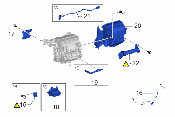
| Procedure | Part Name Code |
|
|
|
|
|---|---|---|---|---|---|
| 15 | NO. 2 AIR CONDITIONING RADIATOR DAMPER SERVO SUB-ASSEMBLY | 87050D | (202307,999999,_58,_104612,_0500007,RM100000002BK0Z_01_0081,)
|
- | - |
| 16 | AIR CONDITIONING HARNESS ASSEMBLY | 82210K | - | - | - |
| 17 | AIR CONDITIONING AMPLIFIER ASSEMBLY | 88650N | - | - | - |
| 18 | HEATER COVER | 87114C | - | - | - |
| 19 | ASPIRATOR | 88897P | - | - | - |
| 20 | BLOWER ASSEMBLY | 87130D | - | - | - |
| 21 | NO. 3 INSTRUMENT PANEL WIRE | 82143C | - | - | - |
| 22 | NO. 2 AIR DUCT | 87211A | - | - | - |
| *A | w/ PTC Heater | *B | w/ Rear Air Duct |
| *C | w/o Rear Air Duct | *D | for Automatic Air Conditioning System |
| ● | Non-reusable part | - | - |
PROCEDURE

 88625
1.INSTALL NO. 1 COOLER THERMISTOR
88625
1.INSTALL NO. 1 COOLER THERMISTOR
88501
2.INSTALL NO. 1 COOLER EVAPORATOR SUB-ASSEMBLY
88515
3.INSTALL COOLER EXPANSION VALVE
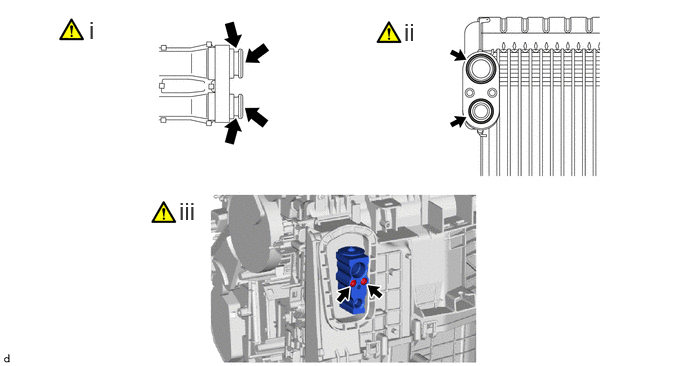
Sufficiently apply compressor oil to 2 new O-rings and the fitting surfaces of the No. 1 cooler evaporator sub-assembly.
- Compressor Oil:
- for Gasoline Model:
ND-OIL 8 or equivalent
- for HEV Model:
ND-OIL 11 or equivalent
Install the 2 O-rings to the No. 1 cooler evaporator sub-assembly.
- NOTICE:
-
Keep the O-rings and O-ring fitting surfaces free of foreign matter.
Using a 4 mm hexagon socket wrench, install the cooler expansion valve with the 2 bolts.
- Torque:
- 3.5 N*m (36 kgf*cm, 31 in.*lbf)
88897K
4.INSTALL COOLER PIPE GROMMET
87107A
5.INSTALL HEATER RADIATOR UNIT SUB-ASSEMBLY
87124B
6.INSTALL HEATER CLAMP
87128
7.INSTALL HEATER GROMMET
87050C
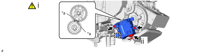
8.INSTALL NO. 1 AIR CONDITIONING RADIATOR DAMPER SERVO SUB-ASSEMBLY (for Automatic Air Conditioning System)
for Dual Type:
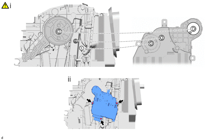
Move the gear of the air conditioner radiator assembly so that the shape of the center gear portion of the air conditioner radiator assembly is aligned with the sensor shaft and output shaft of the No. 1 air conditioning radiator damper servo sub-assembly, and temporarily install the No. 1 air conditioning radiator damper servo sub-assembly as shown in the illustration.
Install the No. 1 air conditioning radiator damper servo sub-assembly with the 3 screws.
for Single Type:
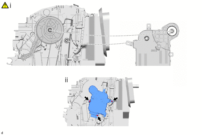
Move the gear of the air conditioner radiator assembly so that the shape of the center gear portion of the air conditioner radiator assembly is aligned with the sensor shaft and output shaft of the No. 1 air conditioning radiator damper servo sub-assembly, and temporarily install the No. 1 air conditioning radiator damper servo sub-assembly as shown in the illustration.
Install the No. 1 air conditioning radiator damper servo sub-assembly with the 3 screws.
9.INSTALL AIR MIX DAMPER CONTROL CABLE SUB-ASSEMBLY (for Manual Air Conditioning System with Mechanical Control Type)
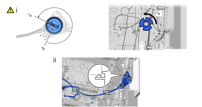
| *a | MAX COLD | *b | MAX WARM |
Set the cable gear and unit gear to the MAX COLD position.
Engage the guides and claws to install the air mix damper control cable sub-assembly.
10.INSTALL HEATER CONTROL CABLE SUB-ASSEMBLY (for Manual Air Conditioning System with Mechanical Control Type)
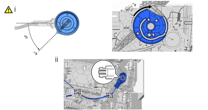
| *a | FACE | *b | 45° |
Set the cable gear and unit link to the FACE position.
Engage the guides and claw to install the heater control cable sub-assembly.
88539J
11.INSTALL DRAIN COOLER HOSE
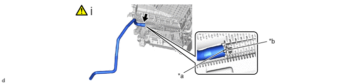
| *a | Hose Notch | *b | Rib |
Align the hose notch with the rib as shown in the illustration and install the drain cooler hose.
87710G
12.INSTALL QUICK HEATER ASSEMBLY (w/ PTC Heater)
87114B
13.INSTALL HEATER COVER (w/o PTC Heater)
87114B
14.INSTALL HEATER COVER (w/ PTC Heater)
87050D
15.INSTALL NO. 2 AIR CONDITIONING RADIATOR DAMPER SERVO SUB-ASSEMBLY (w/ Rear Air Duct)
| *a | Reference Point | - | - |
Using the reference points, engage the guide to install the No. 2 air conditioning radiator damper servo sub-assembly with the 2 screws.
Connect the connector.
82210K
16.INSTALL AIR CONDITIONING HARNESS ASSEMBLY
88650N
17.INSTALL AIR CONDITIONING AMPLIFIER ASSEMBLY
87114C
18.INSTALL HEATER COVER (w/o Rear Air Duct)
88897P
19.INSTALL ASPIRATOR (for Automatic Air Conditioning System)
87130D
20.INSTALL BLOWER ASSEMBLY
82143C
21.INSTALL NO. 3 INSTRUMENT PANEL WIRE (w/ PTC Heater)
87211A
22.INSTALL NO. 2 AIR DUCT
|
|
|