PARK ASSIST / MONITORING TOYOTA PARKING ASSIST-SENSOR SYSTEM C1AE187 Ultrasonic Sensor (Front Left Corner) Missing Message
DESCRIPTION
This DTC is output when an open circuit or short occurs in the communication line between a front corner ultrasonic sensor (FL sensor) and the clearance warning ECU assembly, or when a malfunction occurs in a front corner ultrasonic sensor (FL sensor) on the front.
| DTC No. | Detection Item | DTC Detection Condition | Trouble Area |
|---|---|---|---|
| C1AE187 | Ultrasonic Sensor (Front Left Corner) Missing Message | Front corner ultrasonic sensor (FL sensor) lost communication | ·
Front corner ultrasonic sensor (FL sensor) ·
Harness or connector ·
Clearance warning ECU assembly |
WIRING DIAGRAM
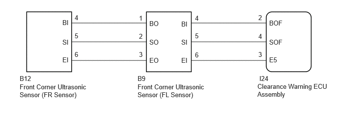
CAUTION / NOTICE / HINT
- NOTICE:
- ·
Perform registration after replacing or removing and installing the ultrasonic sensor or clearance warning ECU assembly.
·If a DTC is detected again after the repair, turn the ignition switch to ON and turn the toyota parking assist-sensor system on, and then clear the DTC.
PROCEDURE
Check the vehicle condition and work details.
- Result:
Result Proceed to The clearance warning ECU assembly or ultrasonic sensor has not been replaced A The clearance warning ECU assembly or ultrasonic sensor has been replaced B
A
B
Check that the connector is properly connected to the front corner ultrasonic sensor and front center ultrasonic sensor.
- Result:
Proceed to NEXT
NEXT
Clear the DTCs.
- Body Electrical > Clearance Warning > Clear DTCs
- 50002 438
- Result:
Proceed to NEXT
NEXT
Check for DTCs.
- Body Electrical > Clearance Warning > Trouble Codes
- 50001 438
- Result:
Result Proceed to DTCs are not output A C1AE187 is output B None of the above conditions are met C
A
B
C
Check that the connector is properly connected to the clearance warning ECU assembly.
- Result:
Proceed to NEXT
NEXT
Clear the DTCs.
- Body Electrical > Clearance Warning > Clear DTCs
- 50002 438
- Result:
Proceed to NEXT
NEXT
Check for DTCs.
- Body Electrical > Clearance Warning > Trouble Codes
- 50001 438
- Result:
Result Proceed to DTCs are not output A C1AE187 and C1AE487 are output B C1AE487 is output C Only C1AE187 is output D None of the above conditions are met E
A
B
C
D
E
Disconnect the I24 clearance warning ECU assembly connector.
Disconnect the B9 front corner ultrasonic sensor (FL sensor) connector.
Measure the resistance according to the value(s) in the table below.
- Standard Resistance:
Tester Connection Condition Specified Condition I24-2 (BOF) - B9-4 (BI) Always Below 1 Ω I24-4 (SOF) - B9-5 (SI) Always Below 1 Ω I24-3 (E5) - B9-6 (EI) Always Below 1 Ω I24-2 (BOF) or B9-4 (BI) - Body ground Always 10 kΩ or higher I24-4 (SOF) or B9-5 (SI) - Body ground Always 10 kΩ or higher I24-3 (E5) or B9-6 (EI) - Body ground Always 10 kΩ or higher
- Result:
Proceed to OK NG
OK
NG
Replace the front corner ultrasonic sensor (FL sensor) with a known good one.
- HINT:
- ·
All of the sensors are interchangeable. To confirm whether a sensor is functioning normally, switch it with a known good sensor from the other end of the vehicle.
- Result:
Proceed to NEXT
NEXT
Clear the DTCs.
- Body Electrical > Clearance Warning > Clear DTCs
- 50002 438
- Result:
Proceed to NEXT
NEXT
Check for DTCs.
- Body Electrical > Clearance Warning > Trouble Codes
- 50001 438
- Result:
Result Proceed to DTCs are not output A C1AE187 is output B None of the above conditions are met C
A
B
C