RM38T0EC _58 Vehicle Interior _112288 LIGHTING (INT) _0510959 LIGHTING SYSTEM J

LIGHTING (INT)  LIGHTING SYSTEM  Interior Light Auto Cut Circuit  


DESCRIPTION

The main body ECU (multiplex network body ECU) controls operation of the DOME CUT relay in order to supply power to the interior lights. When the battery saving function operates while the interior lights are on, the main body ECU (multiplex network body ECU) opens the DOME CUT relay to turn off the lights.

WIRING DIAGRAM
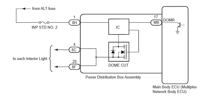
E479608E01
1.156,0.219 2.833,0.448 1.677,0.229 10 false from ALT fuse 1.135,0.896 2.344,1.229 1.208,0.333 10 false INP STD NO. 2 3.885,2.26 4.802,2.458 0.917,0.198 10 false DOME CUT 5.844,0.635 6.76,0.833 0.917,0.198 10 false DOMR 5.469,3.042 7.104,3.448 1.635,0.406 10 false Main Body ECU (Multiplex Network Body ECU) 3.063,2.688 5.948,2.875 2.885,0.188 10 false Power Distribution Box Assembly 0.458,2.021 2.104,2.281 1.646,0.26 10 false to each Interior Light 2.583,0.729 3.052,0.917 0.469,0.188 10 false 8H 2.625,0.531 3.094,0.719 0.469,0.188 10 false 1 2.594,2.125 3.063,2.313 0.469,0.188 10 false 20 2.573,2.323 3.042,2.51 0.469,0.188 10 false 8F 2.625,1.51 3.094,1.698 0.469,0.188 10 false 4 4.156,0.896 4.625,1.083 0.469,0.188 10 false IC 5.51,0.521 5.979,0.708 0.469,0.188 10 false 17 5.5,0.719 5.969,0.906 0.469,0.188 10 false MB 2.563,1.708 3.031,1.896 0.469,0.188 10 false 8C

CAUTION / NOTICE / HINT

NOTICE:
·

Inspect the fuses for circuits related to this system before performing the following procedure.

·

Before replacing the main body ECU (multiplex network body ECU), refer to Service Bulletin.*1

*1: w/ Smart Entry and Start System


PROCEDURE

1.CHECK HARNESS AND CONNECTOR (POWER SOURCE - POWER DISTRIBUTION BOX ASSEMBLY)
a.

Disconnect the 8H power distribution box assembly connector.


b.

Measure the voltage according to the value(s) in the table below.

Standard Voltage:
Tester Connection Condition Specified Condition
8H-1 - Body ground Ignition switch off 11 to 14 V


Result:
Proceed to
OK
NG


OK

2.CHECK POWER DISTRIBUTION BOX ASSEMBLY

NG

REPAIR OR REPLACE HARNESS OR CONNECTOR

2.CHECK POWER DISTRIBUTION BOX ASSEMBLY
a.

Connect the 8H power distribution box assembly connector.


b.

Measure the voltage according to the value(s) in the table below.

Standard Voltage:
Tester Connection Condition Specified Condition
8C-4 - Body ground Always 11 to 14 V
8F-20 - Body ground Always 11 to 14 V
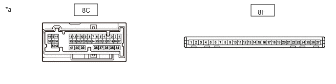

E484321C01
1.583,0.083 2.083,0.333 0.5,0.25 5.354,0.094 5.854,0.344 0.5,0.25 0.115,0.115 0.427,0.313 0.313,0.198 10 false *a 1.75,0.135 2.063,0.333 0.313,0.198 10 false 8C 5.5,0.177 5.813,0.375 0.313,0.198 10 false 8F
*a Component with harness connected
(Power Distribution Box Assembly)
- -


Result:
Proceed to
OK
NG


OK

NG