RM38T0EC
_59
Vehicle Exterior
_113746
DOOR / HATCH
_0510840
POWER BACK DOOR MAIN SWITCH
G
DOOR / HATCH POWER BACK DOOR MAIN SWITCH INSPECTION
PROCEDURE

 84966A
1.INSPECT NO. 1 POWER BACK DOOR CONTROL SWITCH
84966A
1.INSPECT NO. 1 POWER BACK DOOR CONTROL SWITCH
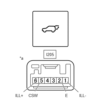
1.49,1.708 1.906,1.99
0.417,0.281
2.094,2.781 2.24,3.115
true
1.354,2.813 1.188,3.104
true
1.198,2.802 0.802,3.125
true
2.281,2.781 2.667,3.135
true
0.667,1.896 0.979,2.094
0.313,0.198
10
false
*a
1.573,1.771 2.031,2
0.458,0.229
10
false
I205
0.521,3.167 0.969,3.365
0.448,0.198
10
false
ILL+
2.219,3.167 2.667,3.365
0.448,0.198
10
false
E
0.969,3.167 1.417,3.365
0.448,0.198
10
false
CSW
2.698,3.167 3.146,3.365
0.448,0.198
10
false
ILL-
| *a | Component without harness connected
(No. 1 Power Back Door Control Switch) |
| *b | Pushed |
| *c | Not Pushed |
a.
Check the resistance of the No. 1 power back door control switch.
i.
Measure the resistance according to the value(s) in the table below.
- Standard Resistance:
Tester Connection Switch Condition Specified Condition I205-5 (CSW) - I205-2 (E) Free Below 1 Ω I205-5 (CSW) - I205-2 (E) Pushed 10 kΩ or higher
If the result is not as specified, replace the No. 1 power back door control switch.
b.
Check that the switch illuminates.
i.
Apply battery voltage to the No. 1 power back door control switch and check that the switch illuminates.
- OK:
Measurement Condition Specified Condition Auxiliary battery positive (+) → I205-6 (ILL+)
Auxiliary battery negative (-) → I205-1 (ILL-)Illuminates
If the result is not as specified, replace the No. 1 power back door control switch.