DOOR / HATCH BACK DOOR ADJUSTMENT
CAUTION / NOTICE / HINT
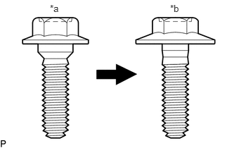
| *a | Centering Bolt |
| *b | Standard Bolt |
- HINT:
- ·
Centering bolts are used to install the door hinges to the vehicle body and door. The door cannot be adjusted with the centering bolts installed. Substitute the centering bolts with standard bolts (with washers) when making adjustments.
·The specified torque for standard bolts is shown in the standard bolt chart.
PROCEDURE

 1.INSPECT BACK DOOR
Check that the clearance measurements of areas A through K are within each standard range.
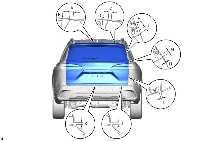
| Area | Measurement | Area | Measurement |
|---|---|---|---|
| A | 7.9 to 10.9 mm
(0.3110 to 0.4291 in.) |
B | -0.5 to 2.5 mm
(-0.0197 to 0.0984 in.) |
| C | 7.9 to 10.9 mm
(0.3110 to 0.4291 in.) |
D | -0.5 to 2.5 mm
(-0.0197 to 0.0984 in.) |
| E | 3.6 mm
(0.1417 in.) |
F | 6.5 mm
(0.2559 in.) |
| G | 4.4 to 7.4 mm
(0.1732 to 0.2913 in.) |
H | -1.3 to 1.7 mm
(-0.0512 to 0.0669in.) |
| I | 5.5 mm
(0.2165 in.) |
J | 6.0 mm
(0.2362 in.) |
| K | 6.0 mm
(0.2362 in.) |
- | - |
2.ADJUST BACK DOOR
Loosen the 4 hinge bolts on the back door and adjust the back door position.
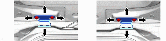
Tighten the 4 hinge bolts on the back door after adjustment.
- Torque:
- 19 N*m (194 kgf*cm, 14 ft.*lbf)
Using a T40 "TORX" socket wrench, slightly loosen the 2 striker mounting screws.

Using a brass bar and a hammer, hit the striker to adjust its position.
Using a T40 "TORX" socket wrench, tighten the 2 striker mounting screws after adjustment.
- Torque:
- 23 N*m (235 kgf*cm, 17 ft.*lbf)