NETWORKING LIN COMMUNICATION SYSTEM B278588 Communication between ECUs connected by LIN Bus off
DESCRIPTION
If the certification ECU (smart key ECU assembly) detects a communication error with an ECU connected to the certification bus lines for 7 seconds or more, DTC B278588 will be stored.
| DTC No. | Detection Item | DTC Detection Condition | Trouble Area |
|---|---|---|---|
| B278588 | Communication between ECUs connected by LIN Bus off | ·
Errors in LIN communication between ECUs or an open or short in communication lines. ·
The certification ECU (smart key ECU assembly) detects a communication error with an ECU connected to the certification bus lines for 7 seconds or more. |
·
Wire harness or connector ·
ID code box (immobiliser code ECU) ·
Certification ECU (smart key ECU assembly) |
WIRING DIAGRAM
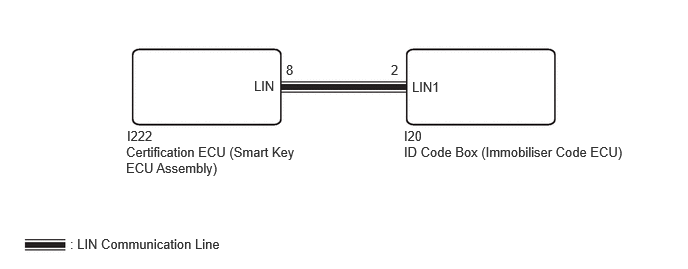
CAUTION / NOTICE / HINT
- NOTICE:
- ·
When using the GTS with the ignition switch off, connect the GTS to the DLC3 and turn a courtesy light switch on and off at intervals of 1.5 seconds or less until communication between the GTS and the vehicle begins. Then select Model Code "KEY REGIST" under manual mode and enter the following menus: Body Electrical / Entry & Start (CAN). While using the GTS, periodically turn a courtesy light switch on and off at intervals of 1.5 seconds or less to maintain communication between the GTS and the vehicle.
·Before replacing the certification ECU (smart key ECU assembly) or ID code box (immobiliser code ECU), refer to Service Bulletin.
PROCEDURE
Disconnect the I222 certification ECU (smart key ECU assembly) connector.
Disconnect the I20 ID code box (immobiliser code ECU) connector.
Measure the resistance according to the value(s) in the table below.
- NOTICE:
-
Make sure that each ECU is in sleep mode before performing the inspection. To enter sleep mode, turn the ignition switch from ON to off and wait for 180 seconds or more without operating any switches.
- Standard Resistance:
Tester Connection Switch Condition Specified Condition I222-8 (LIN) - I20-2 (LIN1) Ignition switch off Below 1 Ω I222-8 (LIN) - Body ground Always 10 kΩ or higher I20-2 (LIN1) - Body ground Always 10 kΩ or higher
- Result:
Proceed to OK NG
OK
NG
Connect the I222 certification ECU (smart key ECU assembly) connector.
Connect the I20 ID code box (immobiliser code ECU) connector.
Clear the DTCs.
- Body Electrical > Entry&Start > Clear DTCs
- 50002 440
- Result:
Proceed to NEXT
NEXT
Check for DTCs.
- Body Electrical > Entry&Start > Trouble Codes
- 50001 440
- Result:
Result Proceed to B278588 is not output A B278588 is output B
A
B