BRAKE SYSTEM (OTHER) VACUUM PUMP(for BOSCH Made) INSTALLATION
CAUTION / NOTICE / HINT
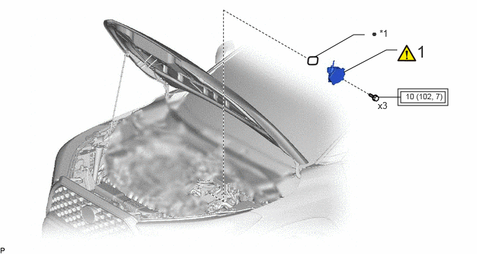
| Procedure | Part Name Code | 
|

|

|
|
|---|---|---|---|---|---|
| 1 | VACUUM PUMP ASSEMBLY | 29300 | ( 202201,999999,_54,_113942,_0505309,RM100000001ZMND_01_0001,) 202201,999999,_54,_113942,_0505309,RM100000001ZMND_01_0001,)
|
- | - |
| *1 | NO. 1 VACUUM PUMP O-RING | - | - |

|
Tightening torque for "Major areas involving basic vehicle performance such as moving/turning/stopping" : N*m (kgf*cm, ft.*lbf) | ● | Non-reusable part |
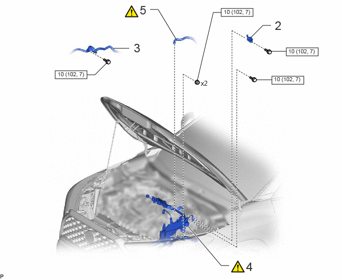
| Procedure | Part Name Code |
|
|
|
|
|---|---|---|---|---|---|
| 2 | NO. 3 WATER HOSE CLAMP BRACKET | 16575F | - | - | - |
| 3 | VACUUM SURGE TANK | 25719 | - | - | - |
| 4 | ENGINE WIRE | 82121 | (202201,999999,_54,_113942,_0505309,RM100000001ZMND_01_0041,)
|
- | - |
| 5 | NO. 1 VACUUM HOSE CONNECTOR | 44777 | (202201,999999,_54,_113942,_0505309,RM100000001ZMND_01_0046,)
|
- | - |

|
N*m (kgf*cm, ft.*lbf): Specified torque | - | - |
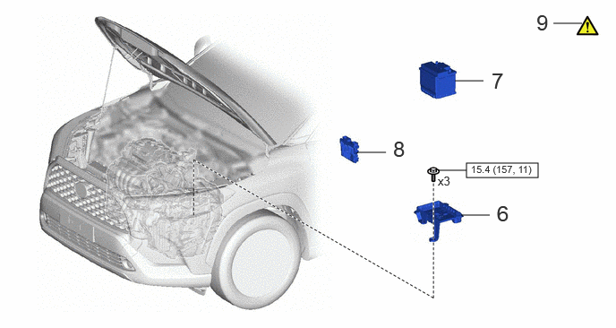
| Procedure | Part Name Code |
|
|
|
|
|---|---|---|---|---|---|
| 6 | BATTERY CLAMP SUB-ASSEMBLY | 74404A | - | - | - |
| 7 | AUXILIARY BATTERY | - | - | - | - |
| 8 | ECM | 89661 | - | - | - |
| 9 | INSPECT VACUUM PUMP OPERATION | - | (202201,999999,_54,_113942,_0505309,RM100000001ZMND_01_0004,)
|
- | - |
|
|
N*m (kgf*cm, ft.*lbf): Specified torque | - | - |
CAUTION / NOTICE / HINT
- NOTICE:
-
This procedure includes the installation of small-head bolts. Refer to Small-Head Bolts of Basic Repair Hint to identify the small-head bolts.
- HINT:
-
Refer to the following illustration and check which type is installed to the vehicle.
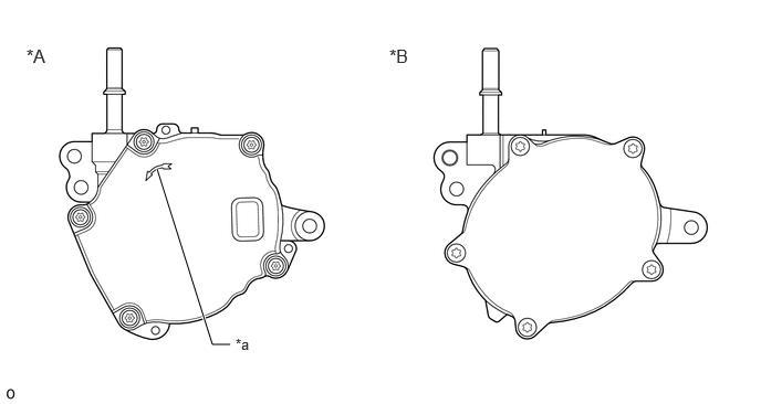 2.167,3.25 2,3.25 2,3.25 1.479,1.594 true 0.25,0.427 0.625,0.667 0.375,0.24 12 false *A 3.667,0.427 4.042,0.667 0.375,0.24 12 false *B 2.219,3.167 2.531,3.365 0.313,0.198 10 false *a
*A for BOSCH Made *B except BOSCH Made *a Mark - -
PROCEDURE

 29300
1.INSTALL VACUUM PUMP ASSEMBLY
29300
1.INSTALL VACUUM PUMP ASSEMBLY
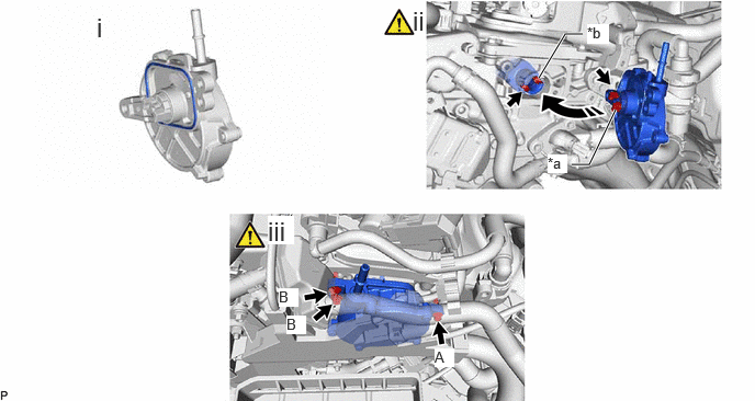
| *a | Coupling Teeth | *b | Groove |

|
Install in this Direction | - | - |
When reusing the vacuum pump assembly:
Install a new No. 1 vacuum pump O-ring to the vacuum pump assembly.
Install the vacuum pump assembly so that the coupling teeth of the vacuum pump assembly and groove of the camshaft are engaged.
- NOTICE:
- ·
Ensure that the vacuum pump assembly is installed securely.
·Be careful not to pinch the No. 1 vacuum pump O-ring.
Using an 8 mm socket wrench, install the vacuum pump assembly with the 3 bolts.
- Torque:
- 10 N*m (102 kgf*cm, 7 ft.*lbf)
- NOTICE:
- ·
Perform the procedure by fully tightening the bolt (A), and then fully tightening the bolts (B).
·After installation, check that there are no gaps between the matching surfaces and that the vacuum pump assembly is not installed at an angle.
16575F
2.INSTALL NO. 3 WATER HOSE CLAMP BRACKET
- Torque:
- 10 N*m (102 kgf*cm, 7 ft.*lbf)
25719
3.INSTALL VACUUM SURGE TANK
- Torque:
- 10 N*m (102 kgf*cm, 7 ft.*lbf)
82121
4.INSTALL ENGINE WIRE
|
|
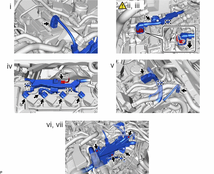
Connect the connector | 
|
Lock the lock lever |
Connect the connector.
Connect the connector and lock the lock lever.
Connect the connector and engage the clamp.
Connect the 6 connectors and engage the 2 clamps.
Connect the 2 connectors and engage the clamp.
Connect the connector and engage the clamp.
Install the engine wire with the bolt and 2 nuts.
- Torque:
- 10 N*m (102 kgf*cm, 7 ft.*lbf)
44777
5.CONNECT NO. 1 VACUUM HOSE CONNECTOR
|
|
|
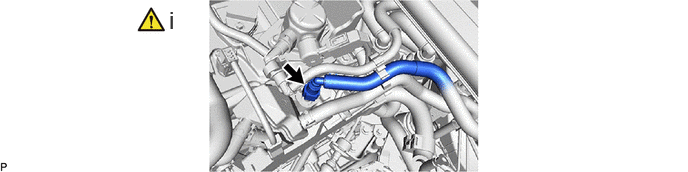
Align the No. 1 vacuum hose connector with the vacuum pump assembly, and push them together until the No. 1 vacuum hose connector makes a "click" sound.
74404A
6.INSTALL BATTERY CLAMP SUB-ASSEMBLY
7.INSTALL AUXILIARY BATTERY
89661
8.INSTALL ECM
9.INSPECT VACUUM PUMP OPERATION