RM38T0EC
_59
Vehicle Exterior
_112294
LIGHTING (EXT)
_0501115
STOP LIGHT SWITCH
A
LIGHTING (EXT) STOP LIGHT SWITCH INSTALLATION
CAUTION / NOTICE / HINT
COMPONENTS (INSTALLATION)
4.615,4.063 4.198,4.063
false
5.625,5.281 5.625,5.031
false
1.281,4.427 1.281,4.177
false
1.719,3.521 1.573,3.521
1.573,3.521 1.521,3.781
false
6.698,5.427 6.906,5.604
0.208,0.177
10
false
x2
5.552,5.313 5.823,5.677
0.271,0.365
18
false
4
5,3.927 5.271,4.292
0.271,0.365
18
false
3
1.177,4.479 1.302,4.688
0.125,0.208
10
false
●
1.292,4.438 1.563,4.802
0.271,0.365
18
false
1
1.99,3.417 2.26,3.781
0.271,0.365
18
false
2
4.865,3.969 4.99,4.177
0.125,0.208
10
false
●
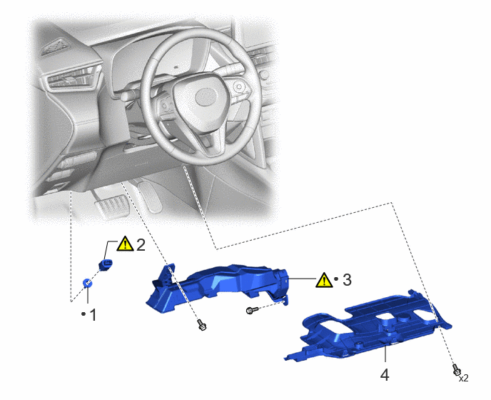
| Procedure | Part Name Code | 
|

|

|
|
|---|---|---|---|---|---|
| 1 | STOP LIGHT SWITCH MOUNTING ADJUSTER | 84345 | - | - | - |
| 2 | STOP LIGHT SWITCH ASSEMBLY | 84340 | ( 202201,999999,_59,_112294,_0501115,RM100000001Z4Y7_01_0072,) 202201,999999,_59,_112294,_0501115,RM100000001Z4Y7_01_0072,)
|
- | - |
| 3 | NO. 1 AIR DUCT | 87211 | (202201,999999,_59,_112294,_0501115,RM100000001Z4Y7_01_0071,)
|
- | - |
| 4 | NO. 1 INSTRUMENT PANEL UNDER COVER SUB-ASSEMBLY | 55606 | - | - | - |
| ● | Non-reusable part | - | - |
PROCEDURE

 84345
1.INSTALL STOP LIGHT SWITCH MOUNTING ADJUSTER
84345
1.INSTALL STOP LIGHT SWITCH MOUNTING ADJUSTER
84340
2.INSTALL STOP LIGHT SWITCH ASSEMBLY
a.
2.156,1.521 1.792,1.271
false
2.198,1.458 2.51,1.656
0.313,0.198
10
false
*1
5.167,1.646 5.479,1.844
0.313,0.198
10
false
*a
1.052,0.26 1.354,0.552
0.302,0.292
18
false
i
5.479,0.094 5.781,0.385
0.302,0.292
18
false
ii
5.813,1.406 6.115,1.698
0.302,0.292
18
false
iii
2.198,1.896 2.438,2.188
0.24,0.292
18
true
iv
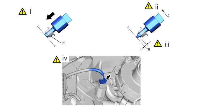
| *1 | Stop light switch mounting adjuster | - | - |
| *a | Protrusion Amount Measurement Area | - | - |
i.
Insert the stop light switch assembly to the stop light switch mounting adjuster until the switch body slightly touches the brake pedal.
- NOTICE:
-
Do not depress the brake pedal.
ii.
Turn the stop light switch assembly clockwise by approximately one fourth of a rotation.
- Torque:
- 1.5 N*m (15 kgf*cm, 13 in.*lbf)
iii.
Check the protrusion amount of the shaft.
- Protrusion amount of the shaft:
Area Measurement Area Measurement a 0.5 to 2.6 mm (0.0197 to 0.102 in.) - -
iv.
Connect the connector.
- NOTICE:
-
Check that the stop light does not come on when the brake pedal is not depressed.
87211
3.INSTALL NO. 1 AIR DUCT
55606
4.INSTALL NO. 1 INSTRUMENT PANEL UNDER COVER SUB-ASSEMBLY