RM38T0EC
_59
Vehicle Exterior
_112294
LIGHTING (EXT)
_0501114
HAZARD WARNING SWITCH
G
LIGHTING (EXT) HAZARD WARNING SWITCH INSPECTION
PROCEDURE

 84330
1.INSPECT HAZARD WARNING SIGNAL SWITCH ASSEMBLY
84330
1.INSPECT HAZARD WARNING SIGNAL SWITCH ASSEMBLY
a.
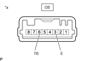
Check that the resistance.
i.
1.49,0.135 1.906,0.385
0.417,0.25
1.25,1.802 1.417,1.219
true
2.167,1.802 2,1.219
true
0.167,0.177 0.479,0.333
0.313,0.156
10
false
*a
1.208,1.833 1.667,2.031
0.458,0.198
10
false
TB
2.167,1.833 2.323,2.031
0.156,0.198
10
false
E
1.594,0.177 2.052,0.375
0.458,0.198
10
false
I38
| *a | Component without harness connected
(Hazard Warning Signal Switch Assembly) |
Measure the resistance according to the value(s) in the table below.
- Standard Resistance:
Tester Connection Condition Specified Condition I38-6 (TB) - I38-3 (E) Hazard warning switch off 10 kΩ or higher I38-6 (TB) - I38-3 (E) Hazard warning switch on Below 50 Ω
If the result is not as specified, replace the hazard warning signal switch assembly.
b.
Check that the illumination lights.
i.

1.49,0.135 1.906,0.385
0.417,0.25
0.948,1.802 1.198,1.219
true
2.417,1.802 2.167,1.219
true
0.167,0.177 0.479,0.333
0.313,0.156
10
false
*a
0.833,1.833 1.448,2.031
0.615,0.198
10
false
ILL+
2.385,1.833 3,2.031
0.615,0.198
10
false
ILL-
1.594,0.177 2.052,0.375
0.458,0.198
10
false
I38
| *a | Component without harness connected
(Hazard Warning Signal Switch Assembly) |
Apply auxiliary battery voltage to the hazard warning signal switch assembly and check that the switch illumination lights comes on.
- OK:
Measurement Condition Condition Specified Condition I38-7 (ILL+) - Auxiliary battery positive (+)
I38-2 (ILL-) - Auxiliary battery negative (-)Always Switch illumination lights comes on
If the result is not as specified, replace the hazard warning signal switch assembly.