RM38T0EC
_59
Vehicle Exterior
_112292
MIRROR (EXT)
_0501089
OUTER REAR VIEW MIRROR
A
MIRROR (EXT) OUTER REAR VIEW MIRROR DISASSEMBLY
CAUTION / NOTICE / HINT
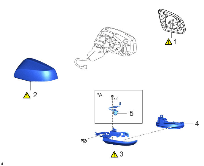
COMPONENTS (DISASSEMBLY)
3.333,3.167 5,4.333
1.667,1.167
6.021,1.333 6.021,1.125
false
4.146,5.323 4.146,5.063
false
6.458,4.354 6.792,4.354
false
4.115,3.979 4.448,3.979
false
1.063,3.177 1.063,2.865
false
3.417,3.229 3.792,3.469
0.375,0.24
12
false
*A
6.094,1.313 6.375,1.667
0.281,0.354
18
false
1
1.167,3.177 1.448,3.531
0.281,0.354
18
false
2
4.198,5.26 4.479,5.615
0.281,0.354
18
false
3
6.854,4.188 7.135,4.542
0.281,0.354
18
false
4
4.552,3.833 4.833,4.188
0.281,0.354
18
false
5
2.917,4.896 3.229,5.094
0.313,0.198
10
false
x2
3.99,3.375 4.302,3.573
0.313,0.198
10
false
x2
| Procedure | Part Name Code | 
|

|

|
|
|---|---|---|---|---|---|
| 1 | OUTER MIRROR | 87961 | ( 202201,999999,_59,_112292,_0501089,RM100000001Z4VV_01_0041,) 202201,999999,_59,_112292,_0501089,RM100000001Z4VV_01_0041,)
|
- | - |
| 2 | OUTER MIRROR COVER | 87945 | (202201,999999,_59,_112292,_0501089,RM100000001Z4VV_01_0048,)
|
- | - |
| 3 | OUTER MIRROR LOWER COVER | - | (202201,999999,_59,_112292,_0501089,RM100000001Z4VV_01_0049,)
|
- | - |
| 4 | SIDE TURN SIGNAL LIGHT ASSEMBLY | 81740 | - | - | - |
| 5 | SIDE TELEVISION CAMERA ASSEMBLY | 86790F | - | - | - |
| *A | w/ Panoramic View Monitor System | - | - |
CAUTION / NOTICE / HINT
- HINT:
- ·
Use the same procedure for the RH side and LH side.
·The following procedure is for the LH side.
PROCEDURE

 87961
1.REMOVE OUTER MIRROR
87961
1.REMOVE OUTER MIRROR
87945
2.REMOVE OUTER MIRROR COVER
3.REMOVE OUTER MIRROR LOWER COVER
a.

0.083,0.083 3.5,2.083
3.417,2
0.167,0.177 0.542,0.417
0.375,0.24
12
false
*A
0.417,0.125 0.698,0.479
0.281,0.354
18
false
i
4.167,0.146 4.448,0.5
0.281,0.354
18
false
ii
0.469,2.313 0.75,2.667
0.281,0.354
18
false
iii
1.719,4.479 2,4.833
0.281,0.354
18
false
v
4.083,2.271 4.365,2.625
0.281,0.354
18
false
iv
| *A | w/ Panoramic View Monitor System | - | - |

|
Remove in this Direction | - | - |
i.
w/ Panoramic View Monitor System:
1. Disconnect the connector.
ii.
Remove the 2 screws.
iii.
Using a screwdriver with its tip wrapped in protective tape, disengage the claws.
iv.
Using a screwdriver with its tip wrapped in protective tape, disengage the claw to remove the outer mirror lower cover as shown in the illustration.
v.
Disconnect the connector.
81740
4.REMOVE SIDE TURN SIGNAL LIGHT ASSEMBLY
86790F
5.REMOVE SIDE TELEVISION CAMERA ASSEMBLY (w/ Panoramic View Monitor System)