STEERING COLUMN STEERING COLUMN ASSEMBLY DISASSEMBLY
CAUTION / NOTICE / HINT
| Procedure | Part Name Code | 
|

|

|
|
|---|---|---|---|---|---|
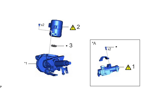
| 1 | UPPER STEERING COLUMN BRACKET WITH SWITCH ASSEMBLY | 45280A | ( 202201,999999,_55,_112306,_0501031,RM100000001Z4RI_02_0030,) 202201,999999,_55,_112306,_0501031,RM100000001Z4RI_02_0030,)
|
- | - |
| 2 | POWER STEERING ECU ASSEMBLY | 89650 | (202201,999999,_55,_112306,_0501031,RM100000001Z4RI_02_0028,)
|
- | - |
| 3 | ELECTRIC POWER STEERING MOTOR SHAFT DAMPER | 45254B | - | - | - |
| *A | w/o Smart Entry and Start System | - | - |
| *1 | ELECTRIC POWER STEERING COLUMN SUB-ASSEMBLY | - | - |
| ● | Non-reusable part | - | - |
| Procedure | Part Name Code |
|
|
|
|
|---|---|---|---|---|---|
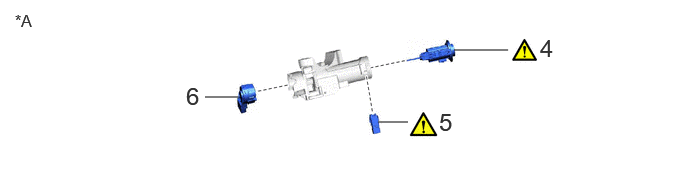
| 4 | IGNITION SWITCH LOCK CYLINDER ASSEMBLY | - | (202201,999999,_55,_112306,_0501031,RM100000001Z4RI_02_0026,)
|
- | - |
| 5 | UN-LOCK WARNING SWITCH ASSEMBLY | 84052 | (202201,999999,_55,_112306,_0501031,RM100000001Z4RI_02_0025,)
|
- | - |
| 6 | IGNITION OR STARTER SWITCH ASSEMBLY | 84450 | - | - | - |
| *A | w/o Smart Entry and Start System | - | - |
CAUTION / NOTICE / HINT
- NOTICE:
- ·
Do not drop the power steering ECU assembly, strike it with tools or subject it to impacts.
·If the power steering ECU assembly is subjected to an impact, replace it with a new one.
·Do not pull the wire harness.
·Do not allow any moisture to come into contact with the power steering ECU assembly.
·Do not loosen any bolts not mentioned in the procedure.
·Do not allow any foreign matter to contaminate the power steering ECU assembly.
PROCEDURE

 45280A
1.REMOVE UPPER STEERING COLUMN BRACKET WITH SWITCH ASSEMBLY (w/o Smart Entry and Start System)
45280A
1.REMOVE UPPER STEERING COLUMN BRACKET WITH SWITCH ASSEMBLY (w/o Smart Entry and Start System)
| *a | Wooden Block | *b | Cloth |

|
Turn | - | - |
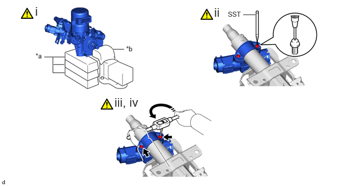
Secure the steering column assembly in a vise using aluminum plates, cloths and wooden blocks.
- NOTICE:
- ·
Do not overtighten the vise, as the steering column assembly may become deformed.
·Secure the power steering ECU assembly so that it is upright.
·Support the steering column assembly with wooden blocks or similar items to ensure that it does not fall.
Using SST, strike a punch mark for drilling in the center of the steering lock set bolt.
- SST
- 09622-00010
- NOTICE:
-
When striking the punch mark, in order to prevent impact force from being applied to the upper steering column bracket with switch assembly, do not use a normal center punch.
Using a drill, drill a hole in the 2 steering lock set bolts and insert a screw extractor.
Using the screw extractor, remove the 2 steering lock set bolts, upper steering column clamp and upper steering column bracket with switch assembly.
89650
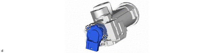
2.REMOVE POWER STEERING ECU ASSEMBLY
45254B
3.REMOVE ELECTRIC POWER STEERING MOTOR SHAFT DAMPER
4.REMOVE IGNITION SWITCH LOCK CYLINDER ASSEMBLY (w/o Smart Entry and Start System)
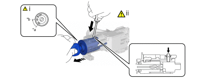
| *a | LOCK | *b | ACC |

|
Push |
|
Remove in this direction |
Turn the ignition switch to ACC.
Insert the tip of a screwdriver into the hole in the upper steering column bracket assembly to remove the ignition switch lock cylinder assembly as shown in the illustration.
84052
5.REMOVE UN-LOCK WARNING SWITCH ASSEMBLY (w/o Smart Entry and Start System)
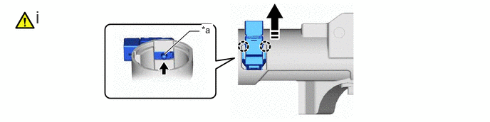
| *a | Center Part | - | - |
|
|
Push |
|
Remove in this direction |
Remove the un-lock warning switch assembly by pushing up the center part and releasing the claws.
84450
6.REMOVE IGNITION OR STARTER SWITCH ASSEMBLY (w/o Smart Entry and Start System)