INTRODUCTION HOW TO USE THIS MANUAL GENERAL INFORMATION
GENERAL DESCRIPTION
Repair operations can be separated mainly into the following 3 processes:
Diagnosis
Removing/Installing, Replacing, Disassembling/Reassembling, Checking and Adjusting
Final Inspection
The following procedures are omitted from this manual. However, these procedures must be performed.
Use a jack or lift to perform operations.
Clean all removed parts.
Perform a visual check before and after performing any work.
PREPARATION
Use of Special Service Tools (SST) and Special Service Materials (SSM) may be required, depending on the repair procedure. Be sure to use SST and SSM when they are required and follow the work procedure properly. A list of SST and SSM is in the "Preparation" section of this manual.
REPAIR PROCEDURES
For component illustrations and procedures, there are 2 types of contents.
For "removal", "installation", "disassembly" and "reassembly":
For "removal", "installation", "disassembly" and "reassembly", the component illustrations include the key points of the procedures and the order in which they are performed.
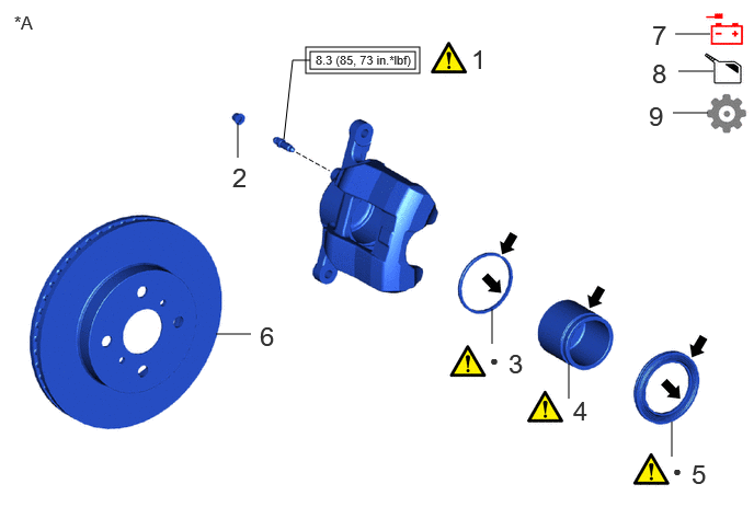
| Procedure | Part Name Code | 
|

|

|
|
|---|---|---|---|---|---|
| 1 | FRONT DISC BRAKE BLEEDER PLUG | - | (Link) | - | - |
| 2 | FRONT DISC BRAKE BLEEDER PLUG CAP | - | - | - | - |
| 3 | PISTON SEAL | - | (Link) | - | - |
| 4 | FRONT DISC BRAKE PISTON | - | (Link) | - | - |
| 5 | CYLINDER BOOT | - | (Link) | - | - |
| 6 | FRONT DISC | 43512 | - | - | - |
| 7 | CONNECT CABLE TO NEGATIVE AUXILIARY BATTERY TERMINAL | - | - | - | - |
| 8 | ADD BRAKE FLUID | - | - | (Link) | - |
| 9 | PERFORM INITIALIZATION | - | - | - | (Link) |
| *A | Example | - | - |

|
Tightening torque for "Major areas involving basic vehicle performance such as moving/turning/stopping": N*m (kgf*cm, ft.*lbf) | 
|
N*m (kgf*cm, ft.*lbf): Specified torque |
| ● | Non-reusable part | 
|
Lithium soap base glycol grease |
The items in the following table are noted in the component illustrations.
| Symbol | Contents |
|---|---|
|
*1: "Major areas involving basic vehicle performance such as moving/turning/stopping" indicates areas that require a higher degree of precision when tightening. *2: "Key points" refers to warnings, notices, SST usage, tightening sequences, etc., basically indicating non-trivial work procedures. |
|
|
|
Tightening torque for "Major areas involving basic vehicle performance such as moving/turning/stopping": N*m (kgf*cm, ft.*lbf)*1 |
|
|
N*m (kgf*cm, ft.*lbf): Specified torque |
| ● | Non-reusable part |
| ★ | Precoated part |
|
|
Apply Lubricant Here |

|
Do not apply lubricants to the threaded parts |
|
|
Indicates key points of the procedure*2 |

|
Disconnect or reconnect negative battery terminal |
|
|
Drain or fill oil/fluid (engine oil, coolant, brake fluid, etc.) |
|
|
Initialize, configure, calibrate, etc. |
Numbers shown in the illustrations and procedure tables indicate the sequence in which steps should be performed.
The included "Part Name Code" is used when searching for the applicable component in the Parts Catalog.
Illustrations of similar vehicle models are sometimes used. In these cases, minor details may be different from the actual vehicle.
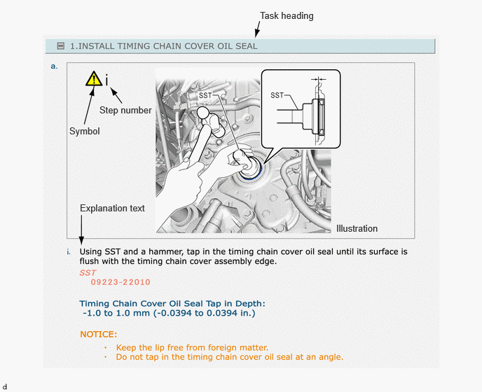
The illustrations show the locations for the work and the work procedures to be performed, while the explanation text includes only those tasks which involve key points, with detailed work instructions, standard values and notices.
| Illustration | What to do and where to do it |
| Task heading | What work will be performed |
| Explanation text | ·
How to perform the task ·
Information such as specifications and warnings, which are written in boldface text |
Step numbers within the illustration indicate the numbers for the explanation text.
Symbols indicate steps with key points.
Procedures are presented in a step-by-step format.
For contents other than "removal", "installation", "disassembly" and "reassembly":
A component illustration is placed under the title where necessary.
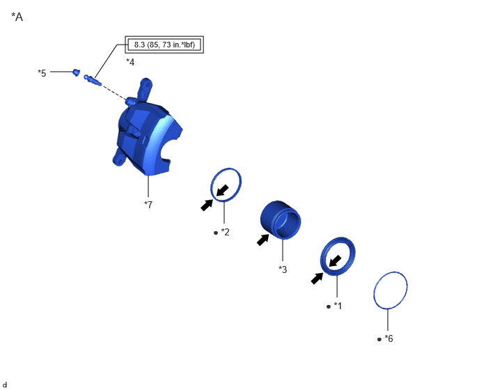
| *A | Example | - | - |
| *1 | CYLINDER BOOT | *2 | PISTON SEAL |
| *3 | FRONT DISC BRAKE PISTON | *4 | FRONT DISC BRAKE BLEEDER PLUG |
| *5 | FRONT DISC BRAKE BLEEDER PLUG CAP | *6 | SET RING |
| *7 | DISC BRAKE CYLINDER ASSEMBLY LH | - | - |
|
|
Tightening torque for "Major areas involving basic vehicle performance such as moving/turning/stopping": N*m (kgf*cm, ft.*lbf) |
|
N*m (kgf*cm, ft.*lbf): Specified torque |
| ● | Non-reusable part |
|
Lithium soap base glycol grease |
The items in the following table are noted in the component illustrations.
| Symbol | Contents |
|---|---|
|
|
Tightening torque for "Major areas involving basic vehicle performance such as moving/turning/stopping": N*m (kgf*cm, ft.*lbf) |
|
|
N*m (kgf*cm, ft.*lbf): Specified torque |
| ● | Non-reusable part |
| ★ | Precoated part |
|
|
Apply Lubricant Here |
|
|
Do not apply lubricants to the threaded parts |
- CAUTION:
-
"Major areas involving basic vehicle performance such as moving/turning/stopping" indicates areas that require a higher degree of precision when tightening.
Non-reusable parts, grease application areas, precoated parts and torque specifications are noted in the component illustrations.
Illustrations of similar vehicle models are sometimes used. In these cases, minor details may be different from the actual vehicle.
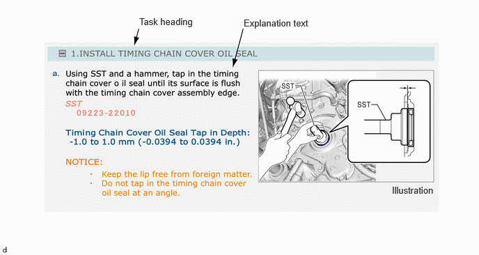
Only items with key points are described in the text. What to do and other details are explained using illustrations next to the text. Both the text and illustrations are accompanied by standard values and notices.
| Illustration | What to do and where to do it |
| Task heading | What work will be performed |
| Explanation text | ·
How to perform the task ·
Information such as specifications and warnings, which are written in boldface text |
Torque specifications, grease application areas and non-reusable parts are emphasized in the procedures.
- HINT:
-
There are cases where such information can only be explained by using an illustration. In these cases, torque, oil and other information are described in the illustration.
Procedures are presented in a step-by-step format.
SERVICE SPECIFICATIONS
Specifications are presented in boldface text throughout the manual. The specifications are also found in the "Specifications" section for reference.
TERM DEFINITIONS
| CAUTION | Possibility of injury to you or other people |
| NOTICE | Possibility of damage to components being repaired |
| HINT | Provides additional information to help you perform repairs |
INTERNATIONAL SYSTEM OF UNITS
The units used in this manual comply with the International System of Units (SI UNIT) standard. Other units from the metric system and the English systems are also provided.
Example:
- Torque:
- 30 N*m (306 kgf*cm, 22 ft.*lbf)